Define Default Wall Conditions
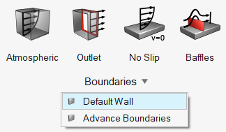
Use the Default Wall tool to edit the default properties of unassigned wall surfaces. If you later assigns properties to a surface, it will be removed from the default domain.
View new features for HyperMesh CFD 2023.1.
Learn the basics and discover the workspace.
Discover HyperMesh CFD functionality with interactive tutorials and community resources.
Solution-centric workflows allow you to traverse through modeling environments using a dedicated UI layer.
Create, open, import, and save models.
Use the Convert tool to convert entire models between data types.
Manage CAD, FE, and 2D parametric sketch geometry.
Generate surface/volume mesh by defining mesh controls, or interactively create and edit 2D surface mesh.
Prepare your model and run the simulation.
Prepare your model for a general AcuSolve simulation.
Set up the simulation model, materials, domains, and boundaries.
Define global simulation settings, materials, and any multipliers or parameters.
Define the simulation domain.
Define surface boundary conditions.
All of the problems in fluid dynamics are governed by the same standard conservation equations. What makes the solution of each problem unique is the set of boundary conditions.
Use the Default Wall tool to edit the default properties of unassigned wall surfaces. If you later assigns properties to a surface, it will be removed from the default domain.
Use the Profiled tool to apply boundary conditions on surfaces where the flow enters the domain.
Use the Constant tool to define an opening surface with a constant velocity.
Use the Pressure tools to enforce pressure on the nodes of a surface.
Use the Far Field tool to define surfaces far away from the source of disturbance.
Use the Atmospheric tool to define atmospheric boundary layers at an inlet.
Use the Outlet tool define boundary conditions on surfaces where flow is exiting the domain.
Use the No Slip tool to define physical walls in the simulation domain.
Use the Baffles tool to define baffle surfaces.
Use the Moving tool to define a surface moving at a certain velocity. This condition then imposes that velocity to the fluid.
Use the Slip tool to define wall surfaces which have zero shear stress and through which there is no normal velocity.
Use the Symmetry tool to define a surface as a symmetry plane.
Use the Periodic tool to define boundaries with translational, rotational, and streamwise periodicity. With a periodic condition, you can represent a larger periodic model by applying settings to just a section.
Use the Advanced Create dialog in the Setup Browser to create boundaries conditions for selected entity groups.
Define radiation conditions and create emissivity models.
Define direct, derived, and constrained mesh motion.
Define output conditions, run the simulation, and view the results.
AcuTrace is particle tracer that runs as a post-processor to AcuSolve.
Prepare your model for wind tunnel analysis using ultraFluidX.
Post-process the simulation results by creating visualizations and measurements.
Automate simulation processes with templates and utility scripts.
Once the baseline model is prepared, you can define morph volumes, morph geometry, create design shapes and run DOE studies. These tool work for both AcuSolve and ultraFluidX-based workflows.
More resources for AcuSolve and ultraFluidX solvers.
Prepare your model and run the simulation.
Prepare your model for a general AcuSolve simulation.
Set up the simulation model, materials, domains, and boundaries.
Define surface boundary conditions.
Use the Default Wall tool to edit the default properties of unassigned wall surfaces. If you later assigns properties to a surface, it will be removed from the default domain.
Use the Default Wall tool to edit the default properties of unassigned wall surfaces. If you later assigns properties to a surface, it will be removed from the default domain.

© 2023 Altair Engineering, Inc. All Rights Reserved.
Intellectual Property Rights Notice | Technical Support | Cookie Consent