Browser Context-Sensitive Menu
The Browser context sensitive pop-up menu offers a variety of operation choices which are relevant to the entity and context.
These options allow you to quickly expand or collapse system/entity folders, save model and assembly files, add assemblies/systems, add entities to containers, rename, activate/deactivate, copy and paste, or delete entities, and view various model information. You can access the context sensitive menu options by clicking the right mouse button on a folder, entity/item, blank space, or column header within the browser.
The visibility of browser context menu items is dependent on the current selection. Only menu items belonging to the type of selected items will appear. Options selected in an empty space apply to the entire model. The items below show the specific context menu options available for each selection:
Model Folder
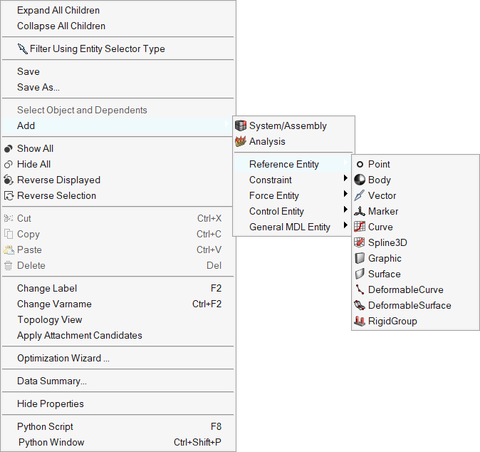
Figure 1. Model folder context menu
System Folder
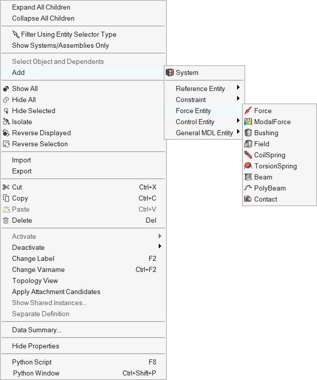
Figure 2. System folder context menu
Assembly placeholder
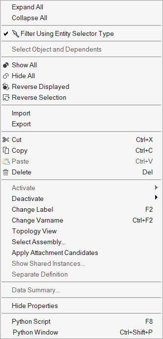
Figure 3. Assembly placeholder context menu
Assembly
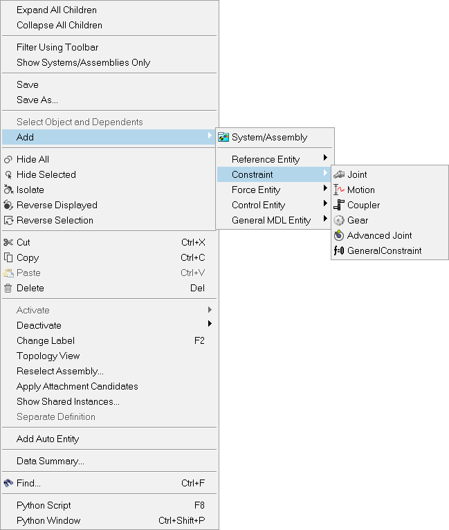
Figure 4. Assembly context menu
Analysis (Inline)
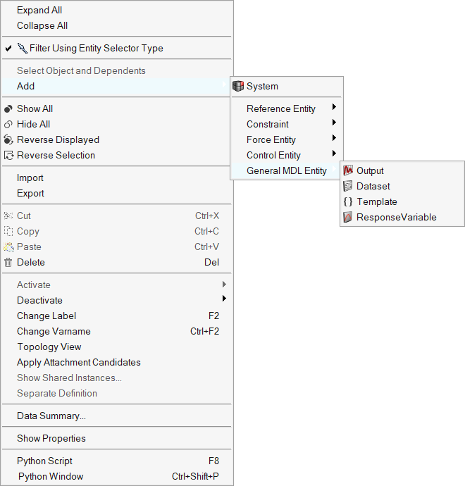
Figure 5. Analysis (Inline) context menu
Analysis (External)
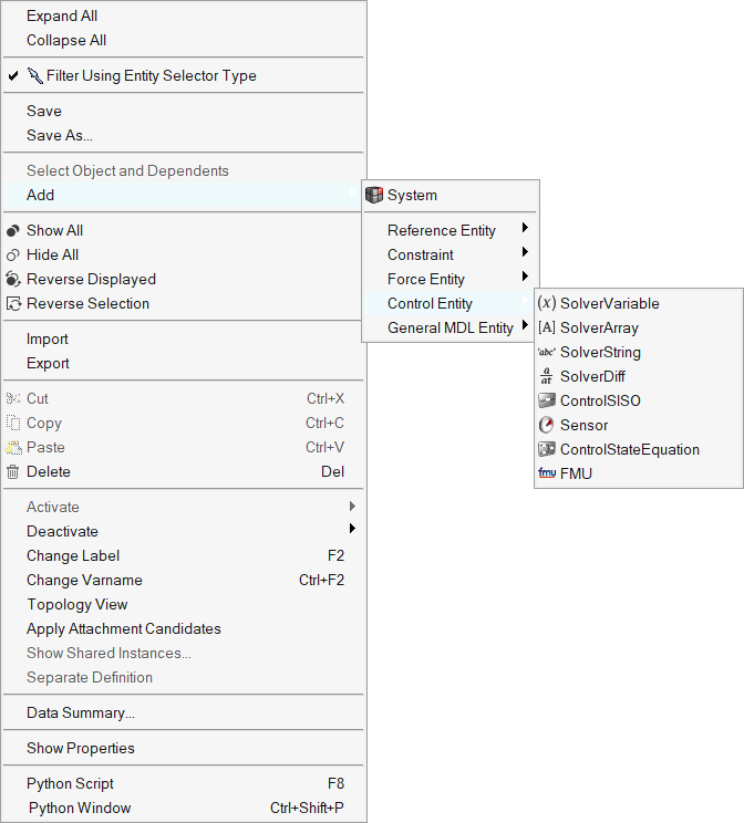
Figure 6. Analysis (External) context menu
"Entity" folder (Body folder, Point folder, etc.)
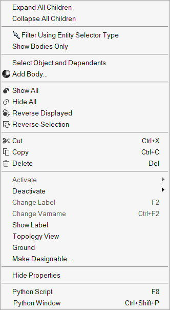
Figure 7. Body folder context menu
"Entity" (Point, Joint, etc.)
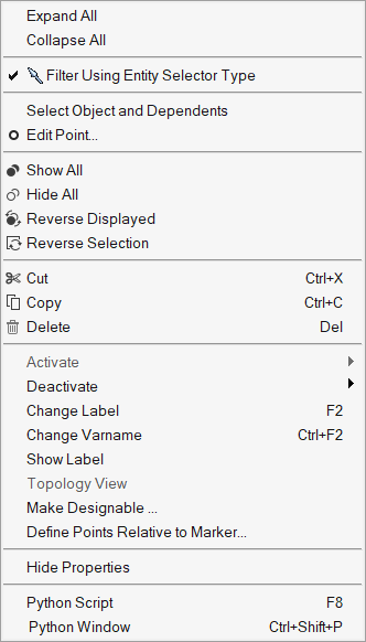
Figure 8. Point context menu
Multiple Bodies
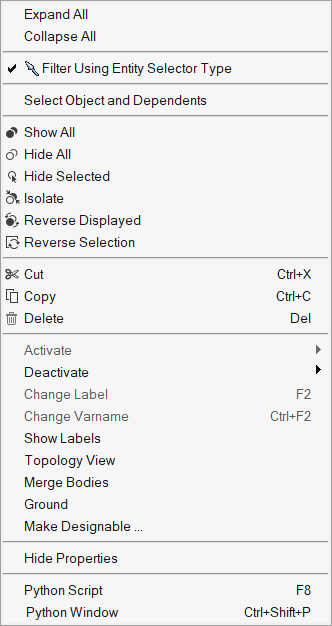
Figure 9. Multiple Bodies context menu
Empty Space
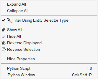
Figure 10. Empty space context menu
Column heading
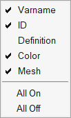
Figure 11. Column heading context menu
| Option | Description | Available for | |
|---|---|---|---|
| Expand All | Fully expands all levels of the browser tree structure to show all items nested in the hierarchy. |
Empty space |
|
| Collapse All | Fully collapses all levels of the browser tree structure to show only the root-level model (system) entity in the hierarchy. |
Empty space |
|
| Expand All Children | Expands selected parent system (or folder container) to show all of its child entities. Opens all of the child entity folders (children), exposing every item nested at every level under the selected system folder (only). |
|
|
| Collapse All Children | Collapses all child entities to show the parent system (or entity container) for the selected entity (or entities). Closes all of the child entity folders (children), so that only the top-most level is displayed for the selected system folder. |
|
|
| Filter Using Entity Selector Type | Allow you to control what types of entities
will be displayed in the project browser tree. When toggled on, the filtering is
driven through the entity
selector instead of the browser. The view will be filtered according to the
currently active entity type selected on the toolbar (for example, Points, Bodies,
Joints, etc.). Note: All 'Show…' filter methods will not be accessible while this
option is enabled.
Unchecking this option immediately removes all filtering (equivalent to the Show All Objects state). |
Empty space |
|
| Show All Objects | Removes all entity-based filter(s) so that all
objects will be displayed in the browser. Note: This option is not available when
the Filter Using Toolbar option is active.
|
Empty space |
|
| Show Systems/Assemblies Only | Browser content is filtered to show only System or Assembly entity types. |
|
|
| Show Analyses Only | Browser content is filtered to show only the Analysis entity type. |
|
|
| Show "Entity" Only | Browser content is filtered to show only the
selected "Entity". Note: More than one type of entity may be filtered
simultaneously (for example, joints and points).
|
|
|
| Save | Opens the Save dialog that will allow you to save a file in the .mdl file format. |
|
|
| Save As | Opens the Save As dialog that will allow you to save a file in the .mdl file format. |
|
|
| Select Object and Dependents | Allows you to select the object and all of its dependent entities with one click. This also works on the entity folder and selects all of the entities in that folder as well as their dependents. |
|
|
| Add "Entity" | Opens the Add "Entity" dialog, allowing you to add an entity to the system or model definition. The name of the dialog changes depending on the entity type selected (for example, Add Body or BodyPair or Add Surface). The icon for this menu button indicates the type of entity to be added. |
|
|
| Add > System/ Assembly | Opens the Add System/Assembly dialog wizard, which allows you to either add a new System, or add an Assembly. When adding an Assembly there are three options: Existing Data File, New Data File, and Specify Data File later (also known as an Assembly Placeholder). |
|
|
| Add > System | Opens the Add System dialog wizard, allowing you to add a new System to an existing system or inlined analysis. |
|
|
| Add > Analysis | Allows you to add new analysis to your model, modify attachments, set initial conditions for an analysis, and set analysis options. |
|
|
| Add > ... | Allows modeling entities to be added to a
model, system, assembly, or analysis. Sub-menus residing below the top level Add menu, include the following: |
||
| Reference Entity > | Allows you to add:
|
|
|
| Constraint > | Allows you to add:
|
|
|
| Force Entity > | Allows you to add:
|
|
|
| Control Entity > | Allows you to add:
|
|
|
| General MDL Entity > | Allows you to add:
|
|
|
| Reload All Curves | Reloads all of the curve data present in the system. |
|
|
| Reload Curve | Reloads the data for selected curve. |
|
|
| Show All | Displays all objects in the modeling window. | ||
| Hide Selected | Hides the selected objects in the modeling window. | ||
| Isolate | Displays only the selected objects, turning their display state to on, and turning all other entities off. When isolating Joints, SpringDampers, Bushings, Force, and Markers, the bodies associated with such entities are also displayed. | ||
| Reverse Displayed | Reverses the objects that are displayed in the modeling window | ||
| Reverse Selection | Reverses the selected objects. | ||
| Cut | Cuts the selected systems or entities from the browser tree. No confirmation pop-up dialog will appear. Items that have been cut from the model may be reinserted by using the Paste option on an appropriate System. |
|
|
| Copy | Copies the selected systems or entities from the browser tree. No confirmation pop-up dialog will appear. Items that have been copied from the model may be reinserted by using the Paste option on an appropriate System. |
|
|
| Paste | Paste puts any (previously cut) entities back into the browser tree at the selected hierarchical location. It is important to note that the Paste operation is not valid and is disabled/'grayed-out' in the "Entity" and "Entity" folder context menus. Container folders will be automatically generated, as needed, in order to accommodate the pasted entities. Any entities pasted more than once will have their varname(s) assigned automatically to ensure that they are unique. |
|
|
| Delete | Deletes the selected systems or entities from
the model and removes them from the browser tree. A pop-up dialog to confirm the
delete operation will appear to prevent accidental deletion of items. If Global
entities (such as a Ground Body or Global Origin point) are included in the
selection, they will be ignored and will not be deleted. Tip: The
DELETE keyboard shortcut can also be used to delete the selected
item(s).
Note: Use the Shift+Delete keys to delete without confirmation.
|
|
|
| Activate > Selected | Activates a previously "deactivated" item or
selection of multiple items. Note: The icon for a "deactivated" item has a dimmed
appearance in the browser tree.
|
|
|
| Activate > Selected and Dependents | Activates the selected deactivated items along with its dependent entities. For example, a deactivated body can be activated along with joints that are defined on the body. | ||
| Activate > Selected and References | Allows you to activate the selected deactivated object(s) and all other deactivated objects that are used as references by the selected object(s) with one click. This also works on the entity folder, for example it activates all of the entities in that folder as well as their references |
|
|
| Deactivate > Selected Only | Deactivates the selected item or items. The dependent entities will still be active. The browser icon for the deactivated item becomes 'dimmed' in appearance. |
|
|
| Deactivate > Selected and Dependents | Allows you to deactivate the selected object(s) and all other objects that are using the selected object(s) as references with one click. This also works on the entity folder, for example it deactivates all of the entities in that folder as well as their dependents. |
|
|
| Change Label | Allows you to rename/change the label for a
single system/entity. After a new name has been provided, use the ENTER key to
complete the rename operation. To abort/cancel the rename operation at any time
during data entry, use the ESC key (or click somewhere away from the data entry
field). Tip: The F2 keyboard shortcut can also be used to invoke the
rename data entry field.
|
|
|
| Show Label | Display the label for the selected entity in the modeling window. |
|
|
| Show Labels | Display the labels for the selected entity folder in the modeling window. |
|
|
| Hide Label | Hide the label for the selected entity in the modeling window. |
|
|
| Hide Labels | Hides the labels for the selected entity folder in the modeling window. |
|
|
| Change Varname | Allows you to rename/change the variable name for a single system/entity. After a new name has been provided, use the ENTER key to complete the rename operation. To abort/cancel the rename operation at any time during data entry, use the ESC key (or click somewhere away from the data entry field). |
|
|
| Topology View | Displays an entity, system or a model in a
schematic form to study the topological connectivity it has with other entities
within or outside of its parent system. Refer to the Topology View topic for additional information. |
|
|
| Merge Bodies | Allows you to merge two or more rigid bodies. Refer to the Merging Bodies topic for additional information. | ||
| Ground | Allows you to change the selected rigid body to a grounded state. |
|
|
| Make Designable... |
Allows you to declare entity data-members as designable. These design variables could be used to perform an optimization using MotionSolve via the Optimization Wizard, or as parameters for a MotionSolve FMU generated from the MotionView model (designable FMU). See the MotionSolve Models as a Functional Mockup Unit (FMU) topic for additional information. Currently supported entities are: Points, Bodies (Rigid and Point Mass), Springs, Bushings, Forces, and Datasets. Depending on the type of entity that is chosen (before invoking the context menu), the Design Variable dialog box (as shown below) will list various tabs filtering each type of entity. To add a design variable using an existing point in the model, select the
Points tab, then select the Point entity and choose the
required datamember(s) from the right side of the dialog, and then press the
"Add" button.
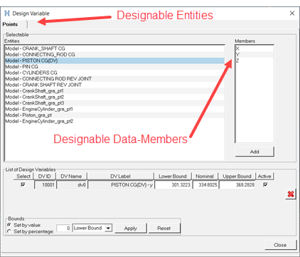 Figure 12. |
||
| Define Points Relative to Marker... | Right-click on points in the browser and use the guide bar to select a marker that will be used to parameterize the location of the currently selected points. | ||
| Select Assembly | Opens the Select Assembly dialog wizard that will allow for swapping out the current assembly for a different one. If the assembly placeholder has a type specified, it will only be possible to choose that type of assembly. |
|
|
| Reselect Assembly | Opens the Reselect Assembly dialog wizard that will allow for swapping out the current assembly for a different one. If the assembly placeholder has a type specified, it will only be possible to choose that type of assembly. |
|
|
| Apply Attachment Candidates | Processes all containers selected (including their children containers) and automatically chooses attachments, where candidates are available as attachments. If there is any ambiguity in selecting an attachment, a pop-up dialog appears allowing the ambiguity to be resolved. Requires usage of Attachment Candidates. See the Container Entities topic for additional information. |
|
|
| Show Shared Instances | Applicable for definition based entities (such
as: Systems, Analysis, Datasets, etc.) that share their definition with other
instances. Lists other instances that share the same definition as the entity
listed under the Definition column. Refer to the Manage Shared Definitions topic for additional information. |
|
|
| Separate Definition | Applicable for definition based entities (such as: Systems, Analysis, Datasets, etc.) that share their definition with other instances. Creates a new definition for the selected entity, thereby separating it from the definition that is shared with the other instances. |
|
|
| Optimization Wizard | Opens the Optimization Wizard, allowing you to
optimize multibody systems. See the Optimization with MotionView and MotionSolve topic for additional information. |
|
|
| Add Auto Entity | Opens the Add Auto Entity
dialog, allowing you to add an auto entity to the model definition. Note: This
option is only available when the "MBD Vehicle Dynamics Tools" preference file
is loaded.
|
|
|
| Add Events | Opens the Add Events
dialog, allowing you to add an event to the model definition. Note: This option is
only available when the "MBD Vehicle Dynamics Tools" preference file is
loaded.
|
|
|
| Data Summary | Displays the Data Summary dialog for the selected item(s) so that the entity type may be inspected in a tabular format. The Data Summary menu button will be disabled (or 'grayed-out') for those entity types that are not supported within the Data Summary table. |
|
|
| Find | Displays the Find Dialog. | All folders and entities. | |
| Python Script | Displays the Python Script dialog. Tip: The F8 keyboard shortcut can also be used to invoke the Python Script
dialog.
|
||
| Python Window | Launches the Python Console. Tip: The Ctrl+Shift+P keyboard shortcut can also be used to invoke the Python
Command Window.
|
||
| Varname | Allows you to show/hide the Varname column. The varname of an entity is commonly used when constructing parametric expressions or when debugging models. | Column heading only. | |
| ID | Allows you to show/hide the ID
column. When enabled, the column displays the current solver ID for all applicable
entities. Pair IDs are shown comma-separated (0,0). Note: You can use the use Check Model tool to generate non-zero ID
values.
|
Column heading only. | |
| Definition | Allows you to show/hide the Definition column. This column displays the definition name for definition based entities such as: System, Assembly, Analysis, DataSets, Templates, Forms, and CommandSets. | Column heading only. | |
| Color | Allows you to show or hide the Color column. When enabled, the color for an entity or a system can be specified by clicking on the color icon and making a selection from the Colors/Materials dialog. When the color of a system is changed, the new color 'cascades down' having an effect on the colors of its children; the colors are updated in both the browser (icons) and in the graphics window. Similarly, changing the color of the 'Model' will effect the color of all systems, as well as their children, therefore this feature should be used with caution. | Column heading only. | |
| Mesh | Allows you to show/hide the Mesh column. When enabled, the mesh and shading attributes for the selected entities can be set by clicking on the mesh icon and making a selection from the Mesh/Shade dialog. The icons in the Mesh column are updated to reflect the settings for a given entity. | Column heading only. | |
| All On | Enables the visibility of all available column headers (Varname, ID, Definition, Color, or Mesh). | Column heading only. | |
| All Off | Disables the visibility of all column headers (except the Objects column, which cannot be turned off). | Column heading only. | |
Finding Entities in the Browser
The Browser is equipped with the ability to search for entities. There are two methods that can be used to search for entities: