Command Sets Panel - Properties Tab
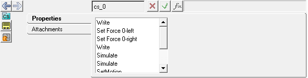
Figure 1. Command Sets panel - Properties tab
Command set types include:
- Write
- Causes the Templex template to be written at that location in the solver command
file.
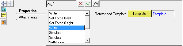
Figure 2. - Forces
- The *SetForce() command set statement writes a force statement to the solver command file. This statement sets the value of the force to the specified value when the solver acts on that line in the command file.
- Simulate
- Exports the simulation commands to the solver command file.
- Motion
- The *SetMotion() command set statement writes a motion statement to the solver command file. This statement sets the value of the motion to the specified value when the solver acts on that line in the command file.
- SetState
- One command set can be active in any one analysis task. MDL saves the state of each command set in the *SetState() statement.