Use the Ejection Mitigation (EM) tool for the automatic target marking according to
FMVSS-226 rules, automatic positioning of the headform impactor, and the automatic export of
ready-to-run solver decks for all of the selected impact locations.
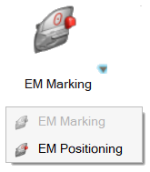
The tool is accessible from the Safety ribbon. A pull-down
menu provides a choice between the Marking and
Positioning workflows. Figure 1.
EM Marking
Click on the guide bar to define
marking options.
Method
Marking methods:
Automatic
The tool performs both vertical and horizontal
orientation marking, as per the regulation.
Horizontal
Only horizontal targets are marked.
Vertical
Only vertical targets are marked.
Front, Second row, Third row
Selection of windows to consider in the marking process.
Vehicle Axis
Orientation of the vehicle -X or +X.
Daylight Offset Distance
Defines the offset distance, as per the regulation.
Dx limit
Minimal distance in X axis considered in the elimination process, as
per the regulation.
Dz limit
Minimal distance in Z axis considered in the elimination process, as
per the regulation.
Absolute D Limit
Minimal distance in case of additional target placement, as per the
regulation.
Apply Rules
When activated, the target elimination process will be performed as
per the regulation. Otherwise, the tool will only mark the 4 initial
targets on the windows.
On the guide bar, click
and to navigate through the selections for the
different windows and frames.
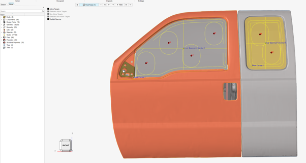
Click Mark to start the target marking process.
The tool will mark the windows and create the targets following the
FMVSS226 regulation rules. Figure 2.
Once the marking is done, a legend is accessible in the top-left corner
of the modeling window. This legend offers
checkboxes to activate/deactivate the visualization of the different targets
calculated during the marking process:
Active Targets
Activates the visualization of the final targets resulting from
the marking process (verticals or horizontals).
Eliminated Active Targets
From the type of active targets, verticals or horizontals,
activates the visualization of the eliminated targets.
Non-Active Targets
Activates the visualization of the other type of targets not
retained as final targets (verticals or horizontals).
Eliminated Non-Active Targets
From the type of non-active targets activates the visualization
of the eliminated targets.
Refer to the protocol for more details.
EM Positioning
After the creation of targets from the marking process, the Positioning workflow is
used to:
Calculate the position of the impactor for all of the selected Design
Points.
Visualize the position of the impactor.
Export ready-to-run solver decks for all of the selected Design Points.
Click on the guide bar to define
marking options.
Vehicle Front Axis
Orientation of the vehicle -X or +X.
Door Side
Defines the impact side.
Move back Distance
Distance between headform impactor and window.
Customized Rotation
If it is activated, it allows to provide a user-defined rotation to
the headform.
Transformation Type
For LS-DYNA:
*NODE_TRANSFORM
*INCLUDE_TRANSFORM
For Radioss:
/GRNODE
//SUBMODEL
Main File
File path to the main input deck to be used for the generation of
the decks.
Headform File
File path to the headform input deck to be used as the include file
in the main input deck.
Output Directory
Directory where all of the solver decks for the selected impact
locations to be simulated will be created.
Design Point name for the directories and include file name
This option takes the name of the Design Point entity for the
creation of subfolders and solver deck names.
Create a folder for each design point in Export Directory
When ON, this option creates a subfolder per the selected Target
Points in the Output Directory location. When OFF, all main decks
and includes are written in the Output Directory location.
On the guide bar, click
and to navigate through the selections to select:
The Glass
Is used to detect the contact point with the headform.
The Headform
All components defining the headform impactor.
The Headform Coordinate System
Will be used to position the headform on the target points. The X
axis of the coordinate system will be aligned with the targets.
Design Points
The targets to be considered for the impact simulations.
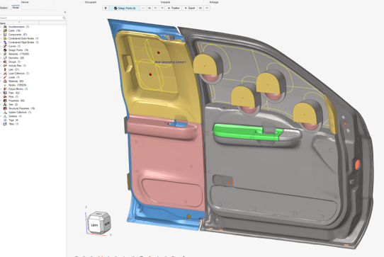
Click Position to visualize the position of the headform
for all of the selected targets.
Figure 3.
Click Export to generate the ready-to-run solver decks
for all of the selected targets.
 on the guide bar to define
marking options.
on the guide bar to define
marking options.
 and
and  to navigate through the selections for the
different windows and frames.
to navigate through the selections for the
different windows and frames.