Browsers provide a structured view of model data, which you can use to review, modify, create, and manage
the contents of a model. In addition to visualization, browsers offer features like search, filtering, and sorting,
which enhance your ability to navigate and interact with the model data.
Use the Quick Edit tool to split surfaces and washers, change the category (shared, free, and so on) of edges, create
or delete surfaces and points, project points, and trim fillets.
Use the Preserve Edges tool to ensure that specific component edges and feature lines do not accidentally get discarded during auto cleanup
or batch meshing.
Find symmetrical surfaces or compare selected surface sets for symmetry. You can reorganize found symmetric surfaces
into separate components or delete one subset of a pair of symmetric surface sets.
Perform a model-based CAD-CAD, CAD-FE or FE-FE comparison between two models, or two selections of entities, and find
and report geometrical/shape differences.
FE geometry is topology on top of mesh, meaning CAD and mesh exist as a single entity. The purpose of FE geometry
is to add vertices, edges, surfaces, and solids on FE models which have no CAD geometry.
Tools and workflows that are dedicated to rapidly creating new parts for specific use cases, or amending existing
parts. The current capabilities are focused on stiffening parts.
Use PhysicsAI to build fast predictive models from CAE data. PhysicsAI can be trained on data with any physics or
remeshing and without design variables.
Explore, organize and manage your personal data, collaborate in teams, and connect to other data sources, such as
corporate PLM systems to access CAD data or publish simulation data.
Fix gaps between stitched edges and vertices to make the actual geometry of the
surfaces consistent with the model topology.
From the Topology ribbon, click the arrow next to the
Edit tool set name and select
Geometry Match Topology from the drop-down
menu.
The Geom Match Topology dialog opens.
Using the Entities selector, select geometry to
check.
In the Tolerance field, enter a tolerance to use when
checking the topology of the model for gaps between shared, non-manifold, or
suppressed edges.
If a gap is found to be bigger than the specified tolerance, then the surface
and edge geometries will be morphed parametrically and in 3D, if necessary,
to make the gap smaller than the tolerance. In addition, non-essential
degenerate edges are removed.
Click Apply.
The original geometric entity IDs are also preserved. The same functionality is used
for the Optimize for CAD option in the Geometry Export Options
dialog.
Example: Match Topology
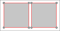
This example demonstrates the difference in results when using the Geom Match
Topology tool to update geometry that has previously been repaired with
topology-based geometry cleanup operations, for example, toggle/equivalence/replace
edges, replace points, and so on.
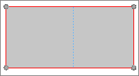
Figure 1. Unrepaired Geometry
The geometry below was repaired using only topology-based geometry cleanup
operations. After the geometry was meshed, you can see that some of the elements
have become distorted. After untoggling the edges, there is still a large gap in the
geometry.
Figure 2. Repaired Geometry not Updated with the Geom Match Topology
Tool
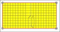
Figure 3. Meshed Geometry
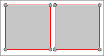
Figure 4. Geometry with Edges Untoggled
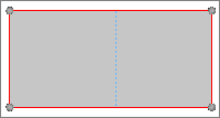
The geometry below was repaired using topology-based geometry cleanup operations and
then updated with the Geom Match Topology tool. After the geometry was meshed, you
can see that there are no distorted elements. After untoggling the edges, there is
not a gap in the geometry.
Figure 5. Repaired Geometry Updated with the Geom Match Topology
Tool