Particle Tracer |

|

|

|

|
|
Particle Tracer |

|

|

|

|
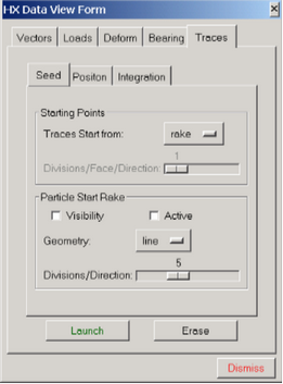
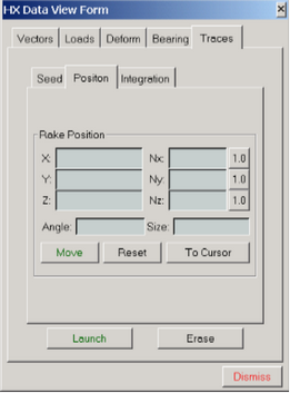
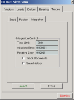
The following panels are used to trace the path of a given particle or set of particles in a vector field. The options contained on this panel allow you to select the type of rake to be used, number of sites associated with the rake, the location of the rake in space and various integration controls.


The Particle Rake and Particle Trace panels
Field |
Description |
Traces Start From |
This option allows you to launch the particles from a rake, inflow, or outflow boundary. |
Divisions/Face/Directions: |
Specifies the number of points to be used one each boundary element face. |
Visibility |
A toggle button to turn the visibility of the particle rake on and off. |
Active |
A toggle button to activate/inactivate the interactive movements of the particle rake controlled by the mouse. When the Active option is turned on, the mouse is set to pan/rotate/zoom the rake instead of the image itself. Toggle the Active option off to return to the standard image manipulation. |
Geometry |
Once the rake activated, this option allows you to select a type of rake to be used (valid options are: point, line, cross, grid, or box). |
Divisions/Directions |
Specifies the number of points to be used in each direction. |
Rake position |
Allows you to directly select the central location of the rake. Once the (x, y, z) coordinates are entered, the Move rake button must be clicked to move the rake to the specified location. The rake's normal orientation (Nx, Ny, Nz) and size cannot be selected directly in the panel. These may only be adjusted using the mouse buttons after turning the toggle button Active on. |
Angle |
Specify the rotation angle to turn a rake. |
Size |
Length of the rake. |
Move |
Moves the rake to coordinates X, Y and Z entered in fields for Rake Position. |
Reset |
Moves the rake the center of the geometry. |
To Cursor |
Moves the rake to position defined by cursor. |
Time limit |
The particle tracking mechanism is a time integration scheme based on the local velocity vector field. The time limit puts an upper bound on the amount of time the integrator will proceed. If too small a time limit is selected, the particle at the rake position may not be integrated sufficiently long enough for your application. In this case, increase the time limit. |
Absolute error and Relative Error |
The time integrator uses two error criteria for controlling the accuracy of the methodology. For most problems the default settings are sufficient. Sometimes, however, the Absolute error value needs to be increased. Try values in the range of 0.1. |
Launch |
Once all of the above settings are in place, the Launch option launches particles from the selected sites. Once the particle tracks are plotted, set the Rake mode to on or off to interactively adjust the view. |
Erase |
Numerous particles can be launched and displayed. To erase all of the particle tracks, click Erase. |
Cancel |
Closes the panel. |