RD-E: 0300 S-Beam Crash
An S-beam is crushed against a rigid wall with initial velocity.
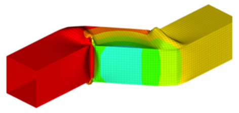
Figure 1.
- Shell element formulations
- BATOZ: Ishell=12
- QEPH: Ishell=24
- Q4 Belytschko: Ishell=3
- Global integration versus 5 integration points in shell element
- Influence of the initial velocity (5 m/s and 10 m/s)
- Deformation configuration
- Crushing force
- Computation cost
- Kinetic energy
- Internal energy
Options and Keywords Used
- Self-impacting contact (/INTER/TYPE7)
- Elasto-plastic material (/MAT/LAW2 (PLAS_JOHNS))
- Initial velocities (/IMPVEL)
- Rigid body (/RBODY)
- Shell section properties (/PROP/TYPE1 (SHELL), Ishell) (element formulation), N (Integration points)
Input Files
Model Description
An S-beam is crushed at an initial rate of 5 m/s against a rigid wall. The section is an empty square-shaped tube (each side measuring 80 mm).
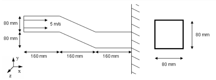
Figure 2. Problem Description and Beam Cross-section
The mesh is a regular shell mesh. Each shell element measures approximately 5 mm x 5 mm.
The following system is used: mm, ms, g, N, MPa
- Material Properties
- Value
- Young's modulus
- 199355
- Poisson's ratio
- 0.3
- Density
- 7.9x10⁻³
- Yield stress
- 185.4
- Hardening parameter
- 540
- Hardening exponent
- 0.32
- Maximum stress
- 336.6
Simulation Iterations
- Shell element formulations:
- BATOZ: Ishell=12 fully-integrated shell element, no hourglassing
- QEPH: Ishell=24 Reduced integration element with physical hourglass stabilization
- Q4 Belytschko: Ishell=3 Reduced integration element with elasto-plastic hourglass with orthogonality
- Through thickness integration method:
- Global integration (N=0)
- 5 integration points (N=5)
- Influence of the initial velocity:
- 5 m/s and 10 m/s
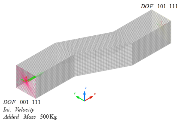
Figure 3. Structure's Overall Mesh
Two rigid bodies were created at the left and right side. Boundary conditions, velocity and added mass are applied on the rigid bodies.
- Fixed in the Z translation, and x, y, z rotation
- Initial velocity of 5 m/s in the X direction
- A 500 Kg mass is added on the left end to the rigid body
Results
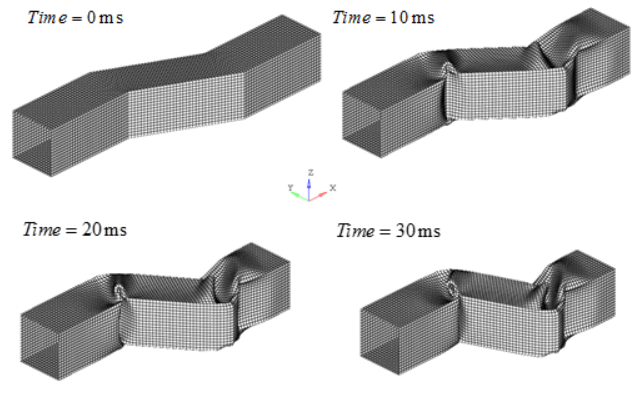
Figure 4. Deformed Mesh for QEPH Formulation. (N=5, V=5 m/s)
Influence of Different Shell Formulation with N=5
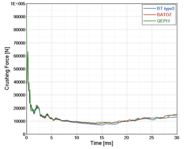
Figure 5. Crushing Force versus Displacement DX for Different Shell Formulations. (N=5, V=5 m/s)
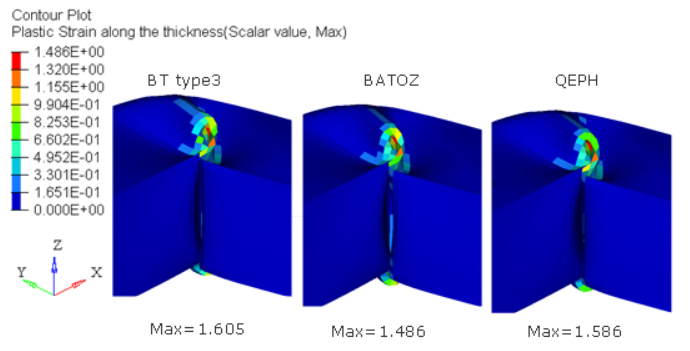
Figure 6. Plastic Strain for Different Shell Formulation. (N=5, V=5m/s)
Influence of Different Integration Points
| 1 CPU [normalized] |
Maximum Plastic Strain | ||
|---|---|---|---|
| BT TYPE3 (Ishell=3) |
N=0 | 0.41 | 0.981 |
| N=3 | 0.56 | 1.596 | |
| N=5 | 0.73 | 1.605 | |
| BATOZ (Ishell=12) |
N=0 | 1.78 | 1.054 |
| N=3 | 2.53 | 1.471 | |
| N=5 | 3.24 | 1.486 | |
| QEPH (Ishell=24) |
N=0 | 0.65 | 0.958 |
| N=3 | 0.78 | 1.516 | |
| N=5 | 1.00 | 1.586 |
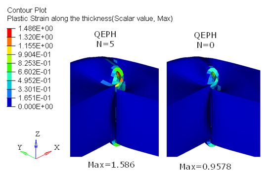
Figure 7. Plastic Strain of QEPH for N=0 and N=5
Initial Velocity Influence
Figure 8 show the influence of the crushing velocity (5 m/s and 10 m/s). This example uses the QEPH shell formulation (Ishell=24) with 5 integration points (N=5).
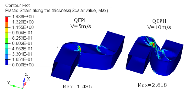
Figure 8. Deformation for the Different Initial Velocities
| Internal Energy
IE [mJ] |
Kinematic Energy
[mJ] |
|
|---|---|---|
| V=5 m/s | 1.674E+6 (factor 1.0) |
4.574E+6 (factor 1.0) |
| V=10 m/s | 4.443E+6 (factor 2.654) |
2.056E+7 (factor 4.495) |

Figure 9. Crushing Force versus Displacement for the Different Initial Velocities
Conclusion
The BATOZ (Ishell=12) and QEPH (Ishell=24) element formulations provide accurate results. Although the Q4 Belytschko (Ishell=3) element is faster, there is always the possibility of hourglassing as shown in RD-E: 0100 Twisted Beam. Although more expensive than the Q4 Belytschko element, the QEPH element does not have the hourglassing issue and provides results that are very similar to the more expensive fully-integrated BATOZ element.
Using global integration (N=0) is faster but not as accurate as using N=5 integration points. The global integration results show an under-estimation of the plastic strain and can only be used with a limited number of material laws.