Use springback tools to define a reference part and constraints in a springback
operation.
Define Reference Part
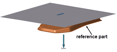
Define a reference part in your model for a springback operation.
The reference part helps to locate any defined constraints on the formed part shape.
This is helpful when a multi stage forming process is required and the formed part
shape before springback is no longer available.
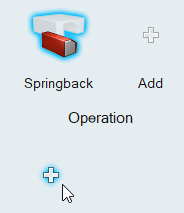
From the Tryout ribbon, select a springback operation that you've added to your
analysis.
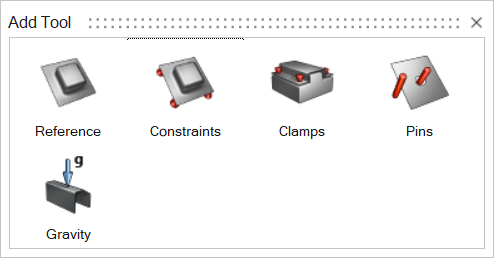
Click the Add Tool button below the springback operation.
Select the Reference tool.
Use the options in the guide bar to specify the reference part.
Double right-click to confirm the reference part.
Define Springback Constraints
Define constraints to hold a part in its designated position during a springback
operation.
You can apply constraints to a single point on the model, to an edge, or a face.
You can define springback constraints only on a meshed blank or reference part that
is either geometry or a mesh representation.
From the Tryout ribbon, select a Springback operation that you've added to your
analysis.
Click the Add Tool button.
Select the Constraints tool.
Follow the guide bar to define the constraints. Begin by clicking a point,
edge, face, or hole on your model.
Hold the Shift key as you click to create a
concentrated point support.
Hold the Ctrl key to apply the support to
multiple features on the same part.
Define constraints at specific X, Y, and Z points.
Place the constraint.
Click
in the microdiolog, then enter values
for X, Y, and
Z.
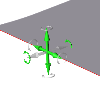
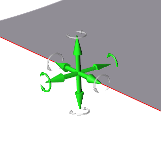
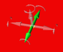
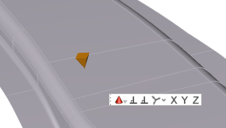
To allow translation in one or more directions for a particular support, click
on a cone for that support. A transparent axis trident appears.
Click on the arrows to toggle the locks on and off in those directions.
A green arrow indicates that translation is allowed in that direction, while a
gray arrow indicates that it is locked.
Right-click and mouse through the check mark to exit, or double-right-click.
Translate
or Rotate Constraints
When you create a support, translation is locked in all directions by default; you
can edit individual supports to allow translation in one or more directions.
Double-click on a support to enter editing mode.
Click the clear axis arrows to enable translation for that axis.
A green arrow indicates translation or rotation is enabled.
Supports applied to a point, line, or face can translate in up to three
directions.
Apply a Constraint to a Cylindrical Hole
Constraints applied to a cylindrical hole are a special case, and have different
properties from constraints applied to a point, edge, or face.
Select the Constraints tool for a springback
operation.
Follow the guide bar to define the constraints. Begin by clicking the interior
of a hole.
Hold the Shift key as you click to create a
concentrated point support.
Hold the Ctrl key to apply the support to
multiple features.
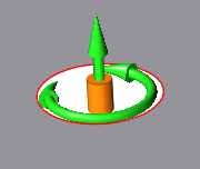
To allow translation or rotation, click on the red support
cylinder.
Transparent graphical handles appear.
Click on the arrows to toggle the locks on and off in those
directions.
A green arrow indicates that translation or rotation is
allowed in that direction, while a gray arrow indicates that it is locked.
Right-click and mouse through the check mark to exit, or double-right-click.
Microdialog
Options
Double-click a constraint to enter editing mode, which opens the Support
microdialog.
Translate or rotate the support using the Move tool. Use to place a support at a
distance.
Align the support normal (perpendicular) to the face.
Align the support normal to the draw direction.
Align the support to the global axes.
Clamps
Add Clamps to your Springback operation.
Select Add Tool.
The Add Tool window appears.
Select the Clamps tool.
In the model, click where you would like to place clamps.
Clamps appear where you click.
Edit the clamp position using the microdialog.
To
Do this
Change the position of the clamp from the top to the
bottom of the model.
Select the Clamp dropdown arrow, then select
Support Tool.
The support tool
moves to the bottom of the model, and the
Toggle clamp position option appears. Click
to switch the position of
the support tool from bottom to top.
Allign the clamp to the selected face.
Select Allign to Face.
Allign the clamp to the draw direction.
Select Align to Draw
Direction.
Align the clamp to the global axis.
Select Global.
Align the clamp to the X axis.
Select .
Align the clamp to the Y axis.
Select .
Align the clamp to the Z axis.
Select .
Right-click and mouse through the check mark to exit, or double-right-click.
Gravity
Add Gravity to a Springback Operation.
Select Add Tool.
The Add Tool window appears.
Select Gravity.
Gravity is added to the operation.
Add and Configure Pins
Add guide pins to your tool set to secure the blank between the top and bottom dies
during a forming operation.
From the Tryout ribbon, select a forming operation that you've added to your
analysis.
The tool set for the operation is displayed.
Next to the tool set, click the Add Tool button.
From the Add Tool dialog that appears, double-click the
Pin tool.
A pin is added to the tool set.
Click the Pin tool.
On the model, select the tool where you want to attach the pin, then click to
confirm.
To place the other end of the pin, select a point or edge on the blank, then
click to confirm.
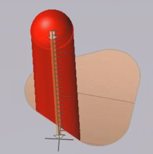
Use the microdialog options to define the pin.
Enter the pin length.
Enter the pin diameter.
To manually define the length of the pin, select
the pin, then click and drag the manipulator up or down.
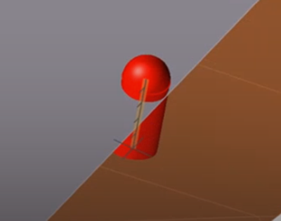
Click the toggle to adjust the pin inward or outward as
required.
If a pin is positioned incorrectly inside the blank, click
the toggle to move the pin outside of the
blank.Figure 1. Incorrect pin position
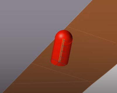
Figure 2. Correct pin position
Click to confirm the pin in the tool set.
The configuration of the pin is complete.
Note:
By default, the pin direction follows the draw direction of the
forming operation. If you change the draw direction, you have to
recreate the pins. The orientation of the pins does not change.
By default, the height of the pin is the distance from the tool
where the pin is attached to the blank at the selected
location.
If you place a pin inside of a hole, Inspire Form automatically
calculates a diameter for the pin. If the hole shape is irregular,
you can adjust the default value set by Inspire Form.
Add more pins
In the guide bar, select Pin. If you have already left
the context of the guide bar, click the existing Pin tool
from the tool set of the forming operation.
Repeat the tasks from Step 5 to configure the pin.
 button below the springback operation.


 in the microdiolog, then enter values
for X, Y, and
Z.
in the microdiolog, then enter values
for X, Y, and
Z.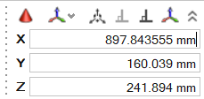
 Supports applied to a point, line, or face can translate in up to three
directions.
Supports applied to a point, line, or face can translate in up to three
directions.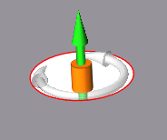

 dropdown arrow, then select
Support Tool.
dropdown arrow, then select
Support Tool. option appears. Click
 .
. .
. .
. .
. .
.
 A pin is added to the tool set.
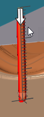
 toggle to adjust the pin inward or outward as
required.If a pin is positioned incorrectly inside the blank, click the
toggle to adjust the pin inward or outward as
required.If a pin is positioned incorrectly inside the blank, click the