ACU-T: 2100 Turbulent Flow Over an Airfoil Using the SST Turbulence Model
Prerequisites
Prior to starting this tutorial, you should have already run through the introductory tutorial, ACU-T: 1000 UI Introduction. To run this simulation, you will need access to a licensed version of HyperMesh CFD and AcuSolve.
Problem Description

Figure 1.
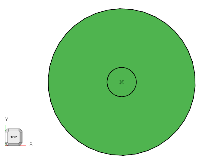
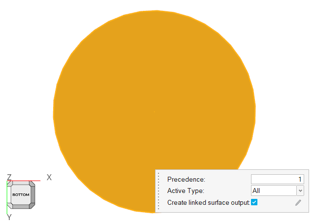
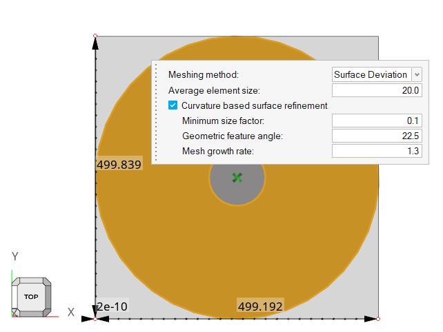
The diameter of the cylindrical bounding volume for the airfoil is set to 500 times the airfoil chord. This large bounding volume is selected to ensure that the farfield boundaries are sufficiently far from the airfoil to prevent any influence of blockage of the domain on the solution.
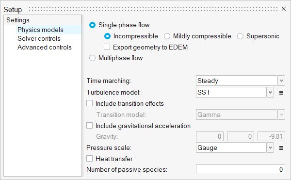
Since the flowfield near the airfoil is assumed to be turbulent, the SST turbulence model will be used for the simulation. These simulation conditions correspond to a scenario where the boundary layer on the leading edge of the airfoil is tripped with some type of roughness elements to produce a fully turbulent boundary layer over the length of the airfoil.
Start HyperMesh CFD and Create the Simulation Database
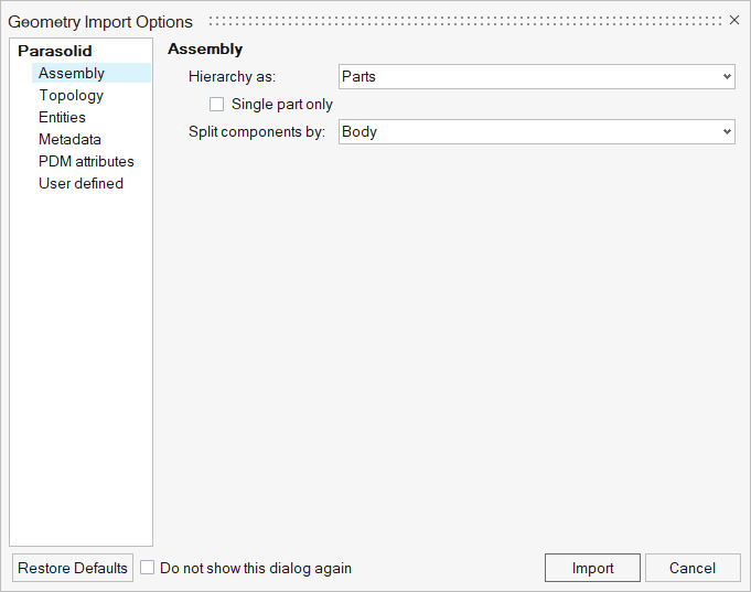
Import the Airfoil Geometry
Validate the Geometry
Set Up the Problem
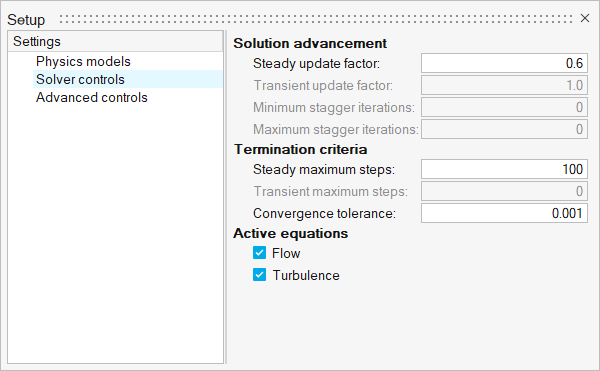
Set Up the Simulation Parameters and Solver Settings
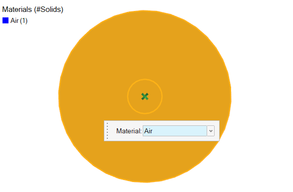
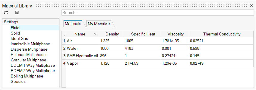
Verify the Material Selection
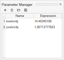
Define Parameters
Assign Flow Boundary Conditions
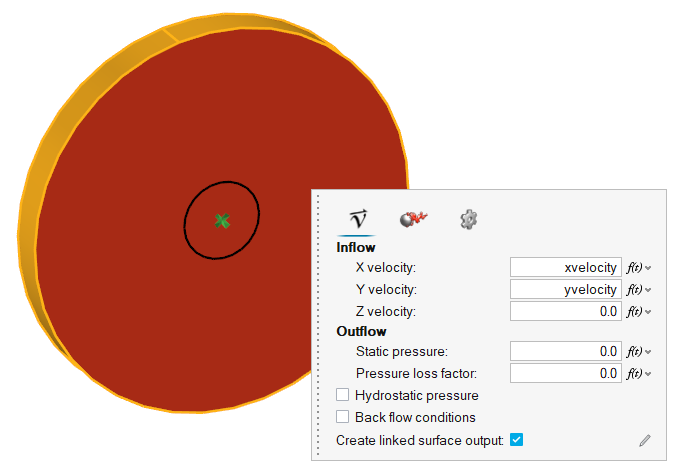
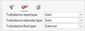
Set a Boundary Condition for the Far Field
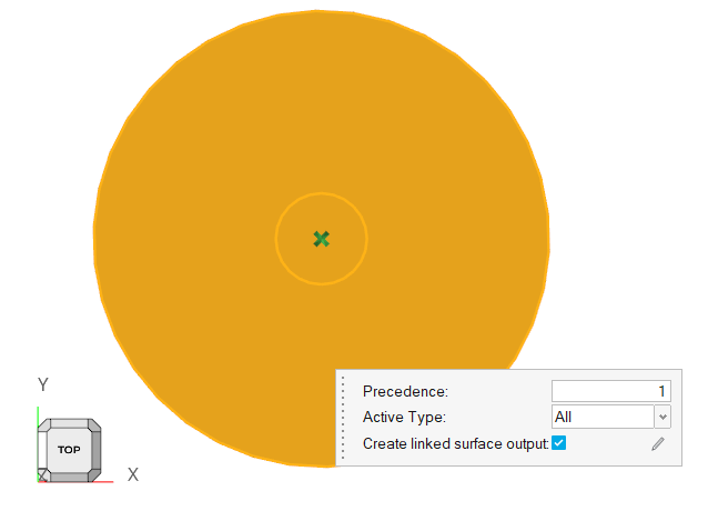
Set Slip Boundary Conditions
Set Wall Boundary Conditions
Define Mesh Properties
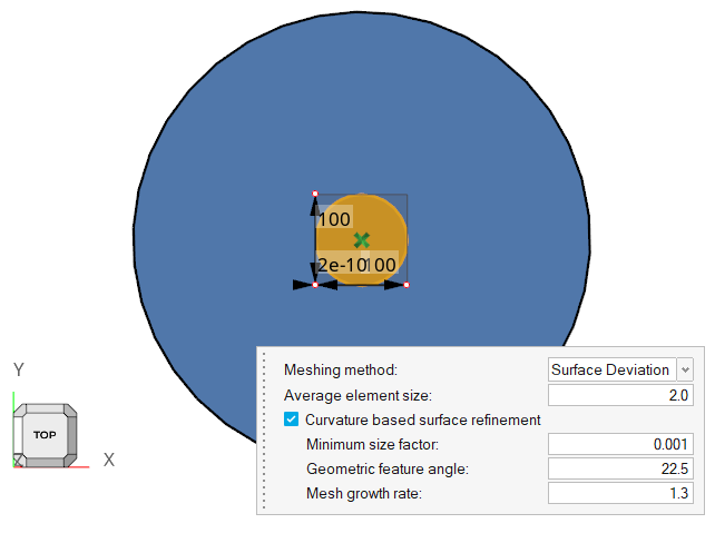
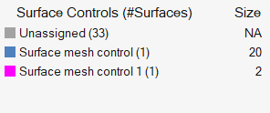
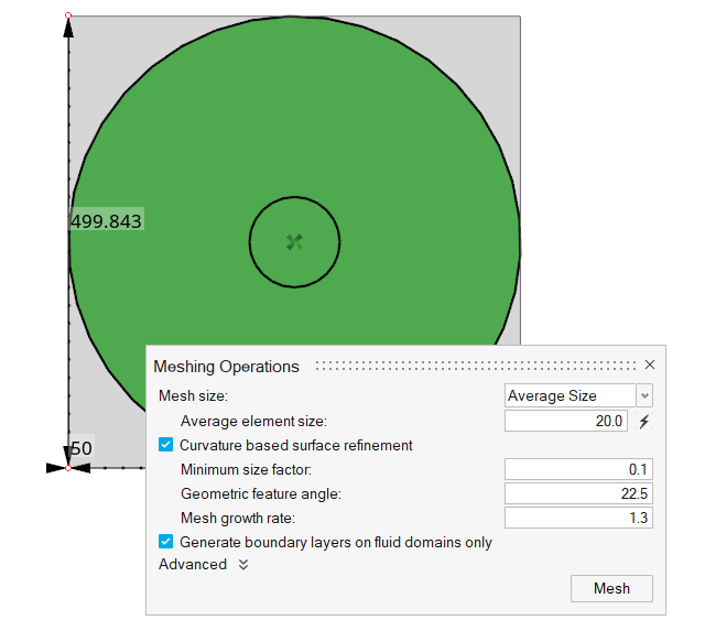
Set Surface Mesh Controls
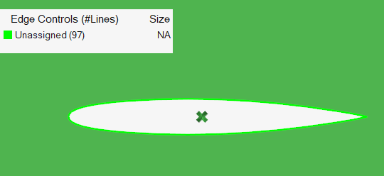
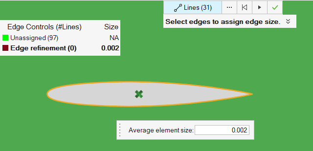
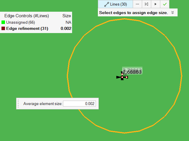
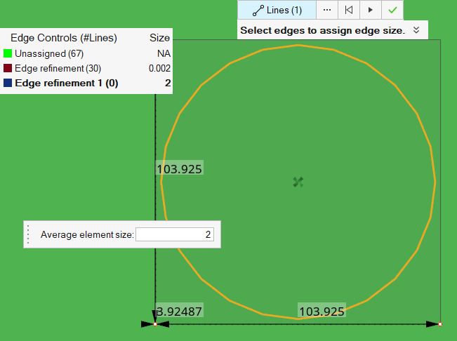
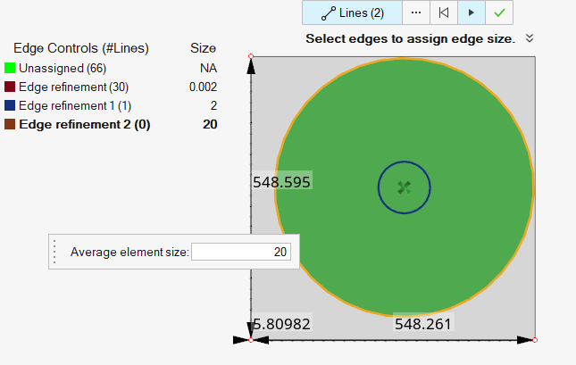
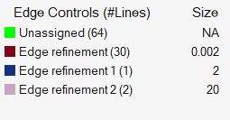
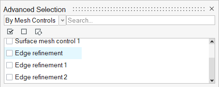
Set Edge Mesh Controls
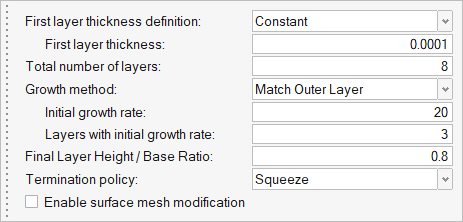
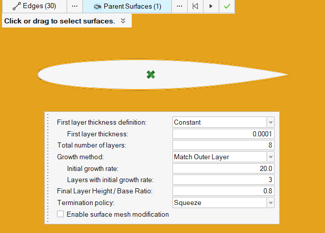
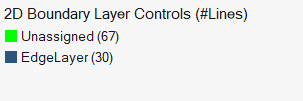
Set Edge Layer Controls
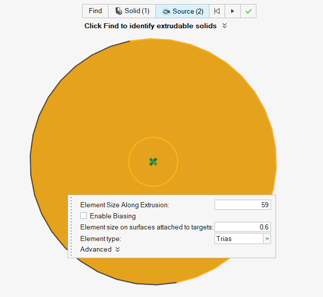
Set Extrusion Controls
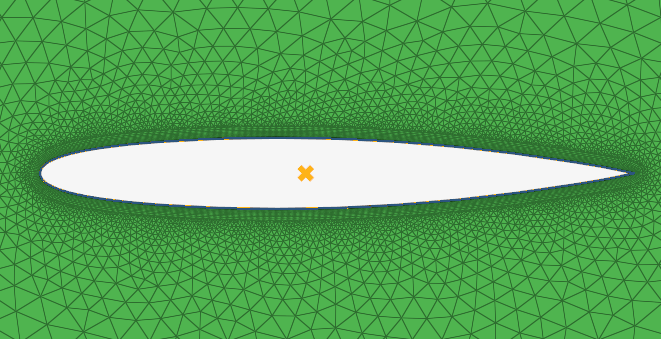
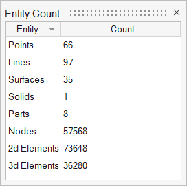
Generate the Mesh
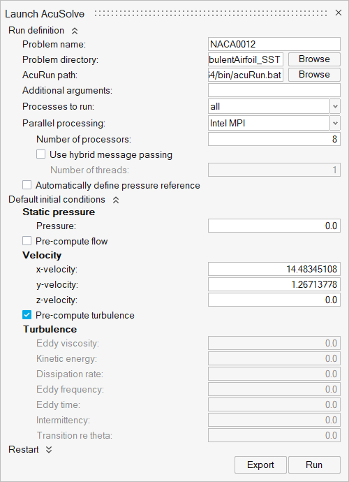
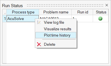
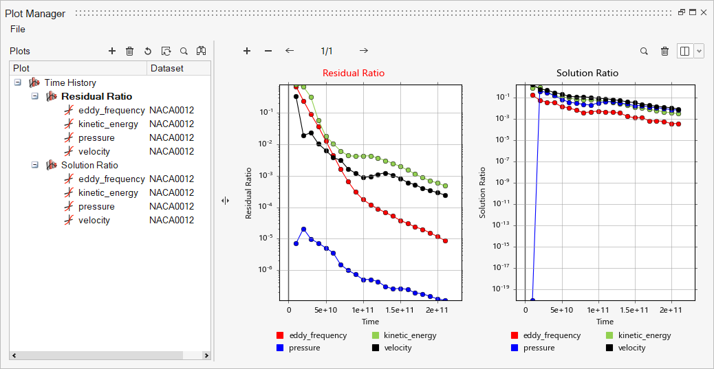
Run AcuSolve
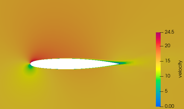
Post-Process the Results with HM-CFD Post
Post-Process to Calculate Flow Coefficients
AcuSolve is shipped with a number of utility scripts to facilitate the pre and post-processing of a problem solved using the solver. You will be introduced to two of these scripts, AcuLiftDrag and AcuGetCpCf in this section, and their usage. These two scripts are focused on aerodynamic simulations as the ones solved in this tutorial.
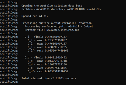
Run AcuLiftGrag
In the Problem Description section, it was described that the simulation is performed as 2D by including only a single layer of extruded elements in the airfoil span direction. When solving a problem in such a way, the span of the airfoil should be set equal to the thickness of the domain in the extrusion direction. When solving a 3D problem, the actual span of the airfoil should be used.
To execute the AcuLiftDrag script for this position, follow the steps below:AcuGetCpCf
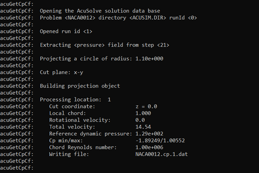
AcuGetCpCf is another utility script used to calculate the coefficient of pressure (Cp) and coefficient of friction (Cf) for the airfoil.
To execute the AcuGetCpCf script for this problem, follow the steps below:
Summary
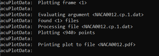
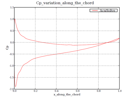
In this tutorial, you learned how to set up and run a NACA0012 airfoil simulation using HyperMesh CFD and AcuSolve. You started by importing the input CAD file. Next, you assigned the flow boundary conditions and generated the mesh using extrusion. Once the solution was computed, you post-processed the results using HyperMesh CFD Post. Finally, you used a utility script of AcuLiftDrag to calculate the lift and drag coefficients of the airfoil and a utility script of AcuGetCpCfto calculate coefficient of pressure (Cp) and coefficient of friction (Cf). The variation of pressure coefficient along the airfoil surface was plotted using a plotting utility acuPlotData.
