ACU-T: 5100 Modeling of a Fan Component Using the Fan Component - Coefficient Method
Prerequisites
This simulation provides instructions for modeling a fan using the classic fan component. Prior to starting this tutorial, you should have already run through the introductory tutorial, ACU-T: 1000 UI Introduction, and have a basic understanding of HyperMesh CFD and AcuSolve. To run this simulation, you will need access to a licensed version of HyperMesh CFD and AcuSolve.
Problem Description
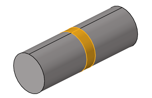
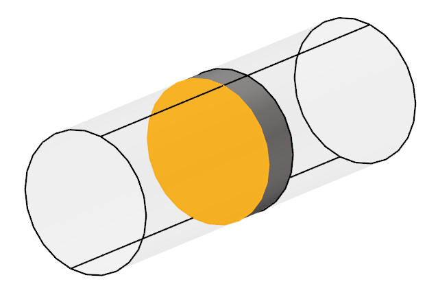
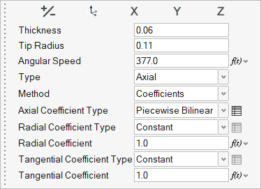
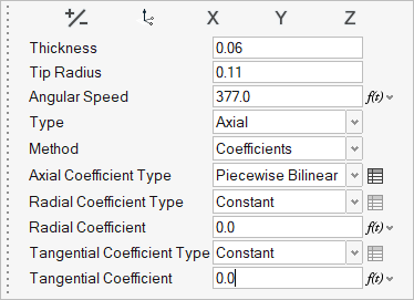
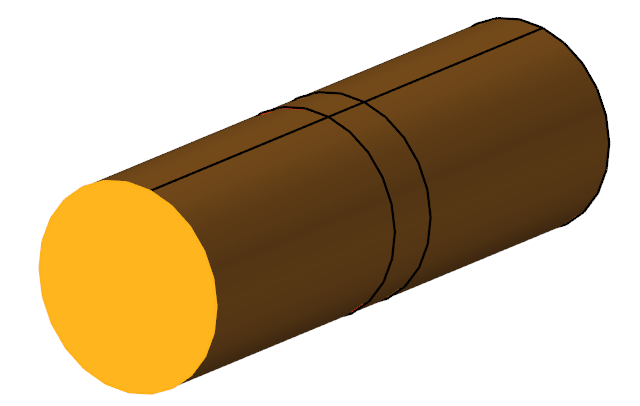
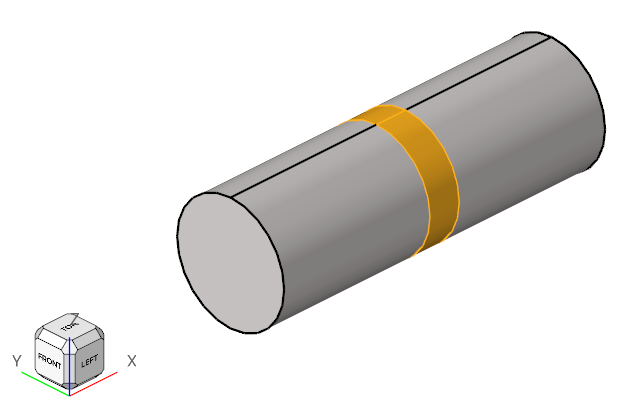
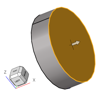
The problem to be solved in this tutorial is shown schematically in the figure below. It consists of an interior fan which rotates at a speed of 377 rad/sec (~3600 RPM) and has a thickness of 0.06 m and a tip radius of 0.11 m. The volumetric flow rate at the inlet is 0.322675 m3/sec (~1161.63 m3/hr). The problem is simulated as a steady state run and the pressure rise across the fan region is computed.

Figure 1.
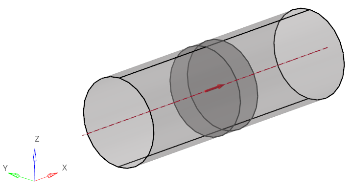
Figure 1 shows a simple axial fan component problem where the fan is an interior fan with thickness “t” and tip radius “r”. In this simulation, flow is passed from the pipe inlet. It enters the fan in an axial direction and exits at the outlet causing pressure rise. This fan pressure rise can be simulated for a given volume flow rate at the inlet surface which will be assigned as the inflow boundary condition. The middle portion of the pipe is the Fan Component which has both Fan_Inlet and Fan_Outlet.
The Fan Component directly computes the body force term to yield the pressure rise within the volume of interest. The body force is applied directly to the volume and not the surface. In order to yield the required pressure rise based on fan performance curve that the you have input, you need to evaluate the volume flow rate correctly at the inlet surface of the domain.
Where:
- - axial coefficient of the fan component
- - tip velocity (m/sec) =
- - fan angular rotational speed (rad/sec)
- - fan tip radius (m)
- - mass averaged velocity (m/sec) through inlet
The fan pressure rise is determined by the fan performance (P-Q) curve which is mainly dependent on the volume flow rate and fan speed for the required fan pressure rise (∆P). Since piecewise_bilinear curve fit values used in the classic FAN_COMPONENT approach are functions of the normalized flow rate and axial coefficient, you need to convert them from the fan performance curve.
Normalized flow rate
- Q - flow rate
- A - area
Axial coefficient
For example, evaluate the axial coefficients and normalized flow rate from the fan performance data. The following tables are inputs for the calculations.
| Fluid Density | 1.225 kg/m3 |
| Tip Radius ( - fan tip radius (m)) | 0.11m |
| Rotational Speed () | 3600 RPM = 376.99 rad/sec |
| Inlet Area, Ai | 0.03801 m2 |
| Tip Velocity () | 41.47 m/sec |
| S.No | Volume flow rate (Q), m3/hr | Pressure rise (dP), Pa |
|---|---|---|
| 1 | 525.35 | 494.91 |
| 2 | 890.21 | 474.63 |
| 3 | 1161.63 | 424.90 |
| 4 | 1272.76 | 389.11 |
| 5 | 1356.57 | 350.42 |
| 6 | 1431.84 | 308.18 |
| 7 | 1494.69 | 268.35 |
| 8 | 1551.39 | 230.89 |
You can calculate the normalized flow rate and axial coefficient for first two volume flow rates (Q) from Table 2. The same procedure is followed for the other volume flow rates.
- For Q = 525.35 m3/hr:
- For Q = 890.21 m3/hr:
In this manner we calculate Ql and αaxial for the remaining volume flow rates, shown in the following table.
| S.No | Normalized flow rate (Ql) | Axial Coefficients (αaxial) |
|---|---|---|
| 1 | 0.0926 | 0.4613 |
| 2 | 0.1569 | 0.426 |
| 3 | 0.2047 | 0.3615 |
| 4 | 0.2243 | 0.3191 |
| 5 | 0.239 | 0.2755 |
| 6 | 0.2523 | 0.229 |
| 7 | 0.2634 | 0.1854 |
| 8 | 0.2734 | 0.1445 |

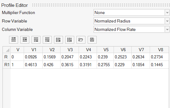
Figure 2. Fan component Array Editor
The first column (0,1) is the normalized radius and the first row (0.0926,…,0.2734) defines the normalized flow rate. The second row data (0.4613,…,0.1445) are for the axial coefficient.
Start HyperMesh CFD and Open the HyperMesh Database
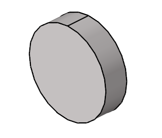
Validate the Geometry
The Validate tool scans through the entire model, performs checks on the surfaces and solids, and flags any defects in the geometry, such as free edges, closed shells, intersections, duplicates, and slivers.

Figure 4.
Set Up Flow
Set the General Simulation Parameters
Assign Material Properties
Define the Fan Component
Define Flow Boundary Conditions
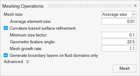
Generate the Mesh
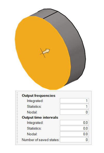
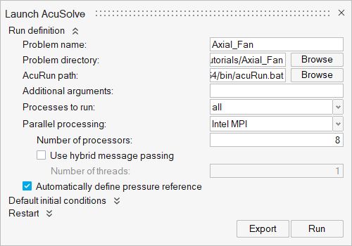
Define Surface Monitors and Run AcuSolve
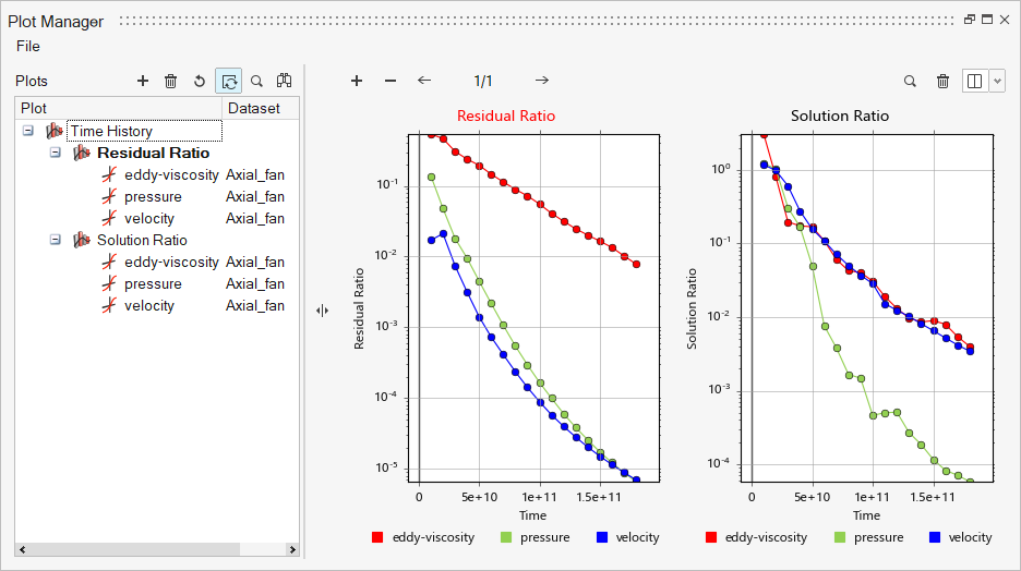
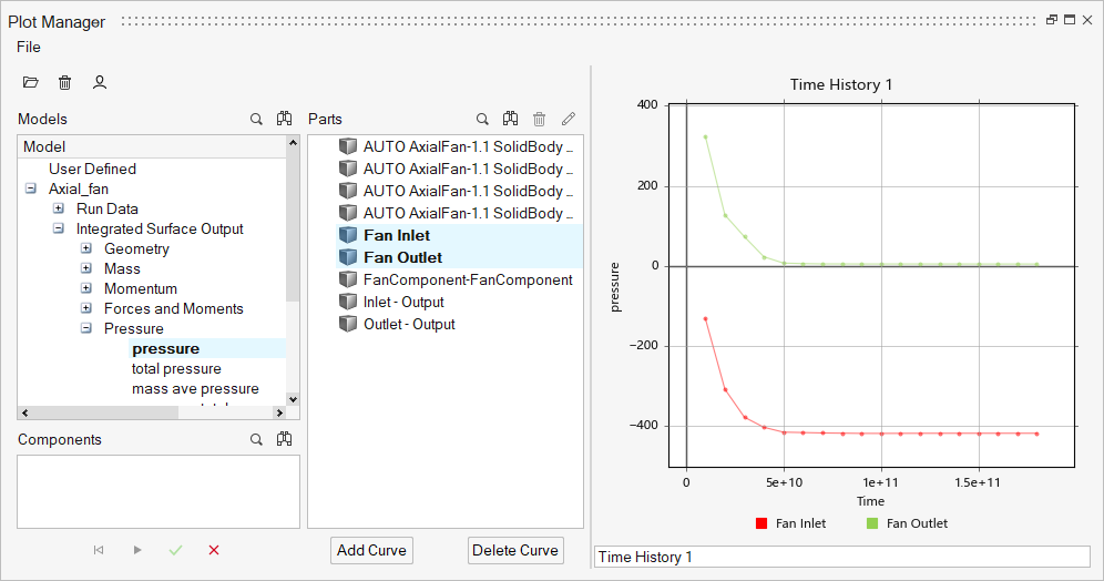
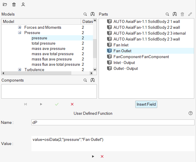
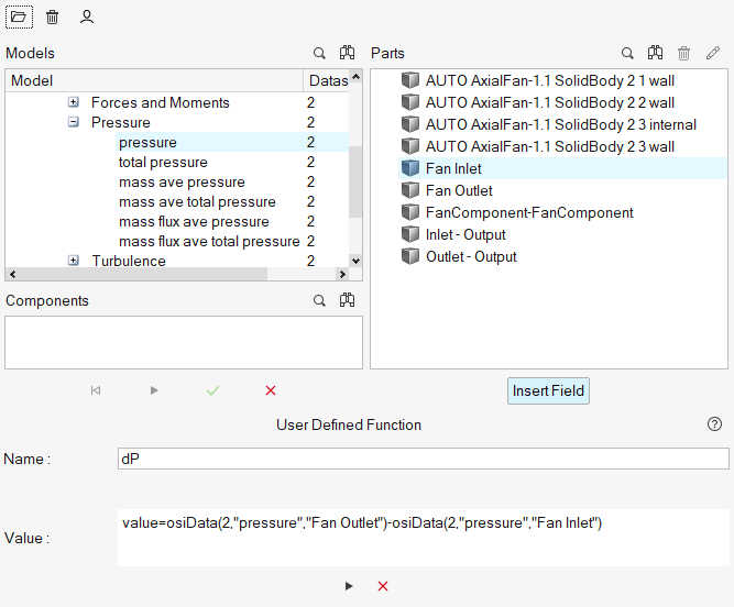
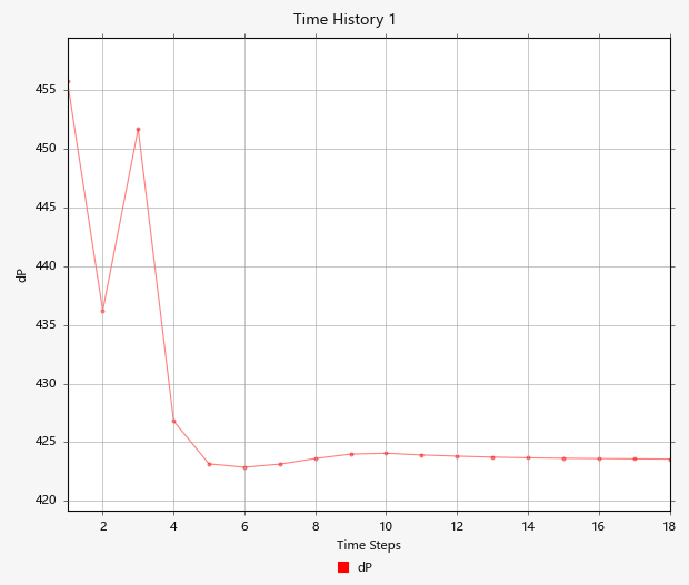
Post-Process with the Plot Tool
Summary
In this tutorial, you successfully learned how to set up and solve a simulation involving a coefficient fan component using HyperMesh CFD. You imported the geometry and then defined the simulation parameters, coefficient fan component, and flow boundary conditions. Once the solution was computed, you used the HM-CFD Plot tool to plot the pressure at fan inlet and fan outlet.


