Create a Line Junction
A Line junction is created to connect two subsystems at an edge.
-
From the Model ribbon, SEA Junctions tool group, click the Line
Junction tool.

Figure 1. -
In the Create Seam Junction Entity Editor, define the
following options.
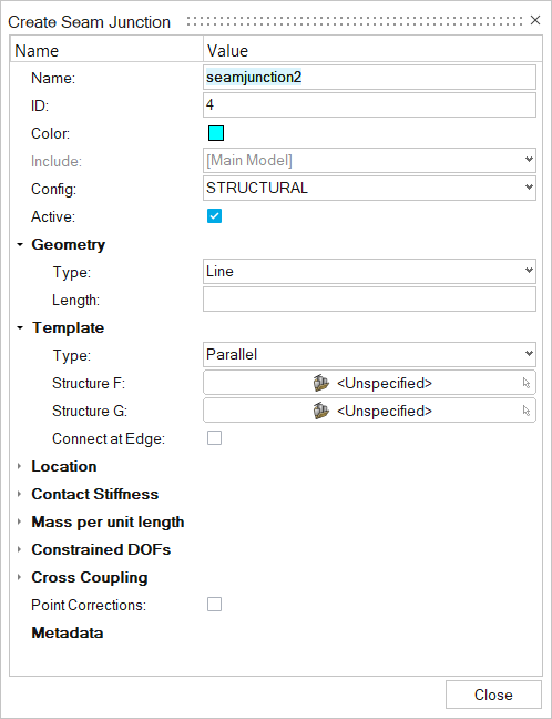
Figure 2.- Name
- Enter a unique name.
- ID
- Enter a unique ID.
- Config
- Specify the element type.
- Geometry
- Based on the element type, update geometry parameters.
- Number
- Enter a number.
- Template
- There are five template types for line junctions.
- Structure F
- Choose the first subsystem.
- Structure G
- Choose the second subsystem.
- Connect at Edge
- Select to connect the edges.
- Location > Lines
- Choose the line where the junction has to be created.
- Contact Stiffness (Single Wall template only)
- To apply a contact stiffness, chose an acoustic space from the drop-down menu and enter a contact stiffness in the second field. This can be used, for example, to model the effect of a ship hull's coating. The coating can be modeled as a spring which isolates the ocean from the vibration of the ship's hull.
- Mass per unit length
- Translational and/or rotational masses at a junction (or mass/length for line junctions) are specified in this section. A junction mass changes the junction impedance, which may reduce or otherwise change the coupling between the elements in the connection. A translational mass changes the junction impedance for all translational degrees of freedom and a rotational mass changes the junction impedance for all rotational degrees of freedom. Frequency-dependent masses may be defined using a function.
- Constrained DOFs
- Structural junctions typically involve translation and rotation through several degrees of freedom (DOF). This option allows you to block energy transmission through any DOF by constraining its motion. Physically, constraining a DOF in SEA means that the elements are free to move (translate or rotate) without causing a reaction or transmitting energy to other elements in the connection. This is opposite of the definition of a constrained DOF in an FEA model, where the elements at the DOF are rigidly constrained to have no relative motion.
- Cross Coupling
- Cross-coupling junctions connect the bending and in-plane subsystems within the same structure. This coupling is observed for real-world structures, even when the junction appears symmetric.