Translate, Rotate, and Position Entities
Use the Move tool to translate, rotate, and position selected entities.
-
From the Home tools, click the Move tool.

Figure 1.In the external aero setup environment, you can also press M or T.
In the general environment, the default move mode is set to Interactive.
- Optional:
In the general environment, click
 on the guide bar to define movement options.
-
Click a graphical manipulator then do one of the following:
- Drag the graphical manipulator to translate or rotate entities in the selected direction(s).
- Enter a precise value in the microdialog and press Enter.
To Do This Translate along an axis Click the X, Y, or Z arrow. 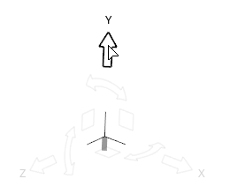
Figure 2.Translate along a plane Click the XY, XZ, or YX plane square. 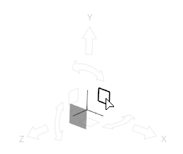
Figure 3.Translate freely in 3D space Click the origin of the Move tool. 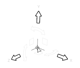
Figure 4.Tip: Use the icons in the microdialog to align the tool to a part or the global axes.Rotate around an axis Click a curved arrow. 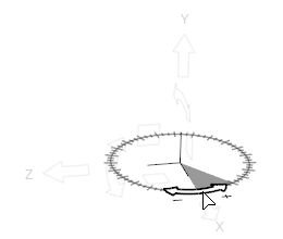
Figure 5.Rotate freely Click  at the tip
of the X, Y, or Z arrow and drag. In the external
aero setup environment, an axis line appears and the
unresolved rotation is prompted on release.
at the tip
of the X, Y, or Z arrow and drag. In the external
aero setup environment, an axis line appears and the
unresolved rotation is prompted on release.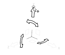
Figure 6.
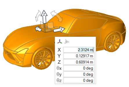
Figure 7.
Reposition the Move Tool
Reposition the Move tool along an axis, within a plane, or in 3D space to change the center of rotation.
-
From the Home tools, click the Move tool.
Figure 8.In the external aero setup environment, you can also press M or T.
In the general environment, the default move mode is set to Interactive.
Microdialog Options
When clicking the Move tool origin:

- Align the Move tool its default orientation and
position:
- Click once to reset its orientation to match the global coordinate system, or local system if one is assigned.
- Click twice to also reset its position to the centroid of your selection, or the local system origin if one is assigned.

- Align the Move tool along an edge or face. If the Move tool is being repositioned (highlighted orange), clicking this button will force the Move tool to be aligned automatically as you drag it around the model.

- Select and assign a local coordinate system to the Move tool. After a new system is assigned, the
Move tool automatically repositions to its
origin.Note: Currently, the Move tool only supports assigning rectangular coordinate systems.
When clicking a translation or rotation arrow:

- Orient the selected direction using the Vector tool.
- Δ
- Use the
 buttons to apply an incremental translation
or rotation in the selected direction.
buttons to apply an incremental translation
or rotation in the selected direction.
Collision Detection
Prevent components from passing through other components.
Figure 9.
Figure 10.
Position Entities using Position Mode
Position entities by specifying source and target locations.
-
From the Home tools, click the Move tool.

Figure 11. - Optional:
Click and select
Show preview to preview the updated position.
-
On the guide bar, complete one of the
following:
- Click
 to apply and stay in the tool.
 - Click
 to apply and close the tool.
 - Click
 to exit the tool without applying.
- Click
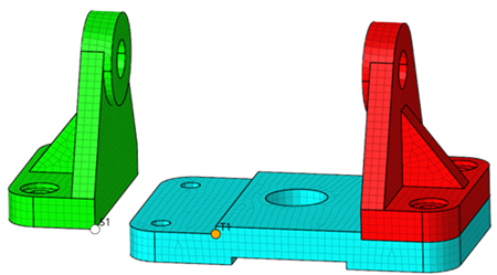
Figure 12.
Figure 13.
Figure 14.
Figure 15. Result
Example: Align Two Solids
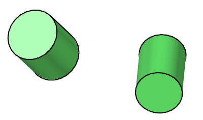
Figure 16.
-
From the Home tools, click the Move tool.
Figure 17. -
Align the tool with the cylinder's face.
-
Drag the origin of the axis to the snap point on the center of the
cylinder's face.
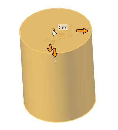
Figure 18. -
Click
 at the tip of the X arrow and drag to a
snap point on the face's edge.
at the tip of the X arrow and drag to a
snap point on the face's edge.
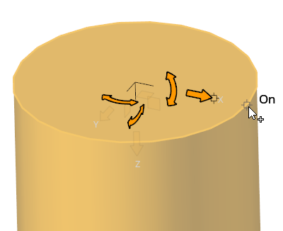
Figure 19. -
Drag the Z axis' curved arrow to a similar snap point on the face's
edge.
By rotating this axis, you lock the other two degrees of freedom.
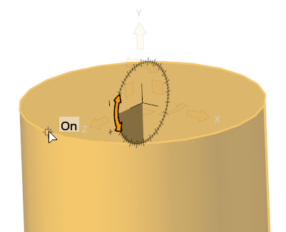
Figure 20.
Tip: It is also possible to automatically align the tool to the selected part by clicking in the microdialog. This works well in many cases, but the
result depends on the position and geometry of the selected parts; so for
complex scenarios, manually repositioning the origin and axes (as shown
above) is a more dependable way of aligning the Move tool. -
Drag the origin of the axis to the snap point on the center of the
cylinder's face.
-
Translate and rotate the cylinder so it aligns with the other.
-
Drag the origin of the axis to the snap point on the surface center of
the other cylinder.
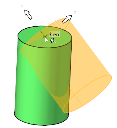
Figure 21. -
Click at the tip of the X arrow and drag to a
snap point on the target face's edge.
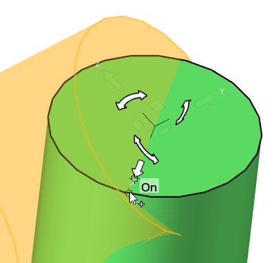
Figure 22. -
Drag the Z axis' curved arrow to a similar snap point on the target
face to finish the alignment.
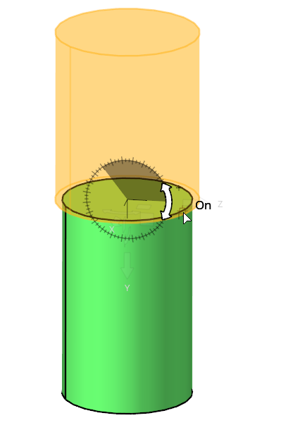
Figure 23.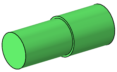
Figure 24.
-
Drag the origin of the axis to the snap point on the surface center of
the other cylinder.