ACU-T: 6000 Static Mixer Simulation – AcuTrace
Prerequisites
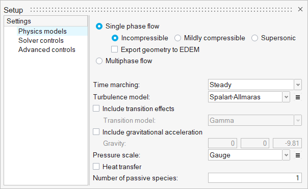
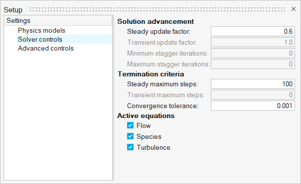
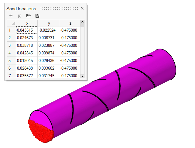
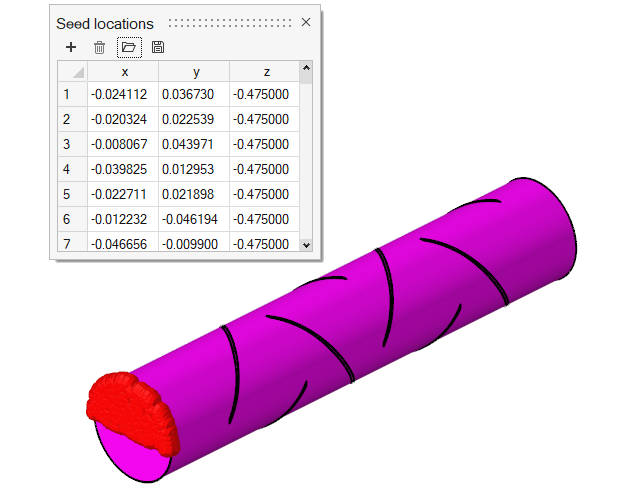
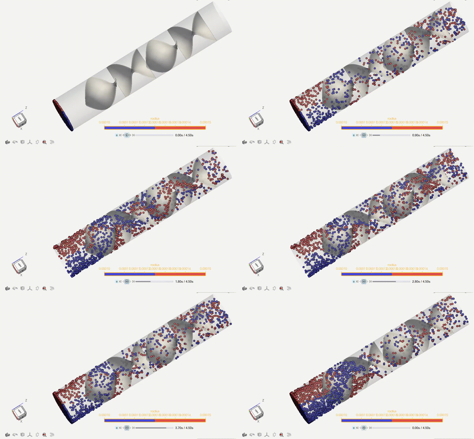
This tutorial provides the instructions for setting up, solving and viewing results for a simulation of a static mixer in combination with the post-processing moduleAcuTrace. In this simulation, AcuSolve is used to compute the species mixing within a simple mixer and AcuTrace is used to compute the particle motion of finite mass particles within the mixer. This tutorial is designed to introduce you to concepts necessary to visualize particulate flow with AcuTrace.
- Generation of finite mass particle with AcuTrace.
- Conversion of the nodal output data with AcuTransTrace for reading into HyperMesh CFD Post.
- Post-processing the nodal output with HyperMesh CFD Post to visualize particles movement.
Problem Description
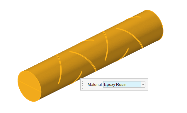
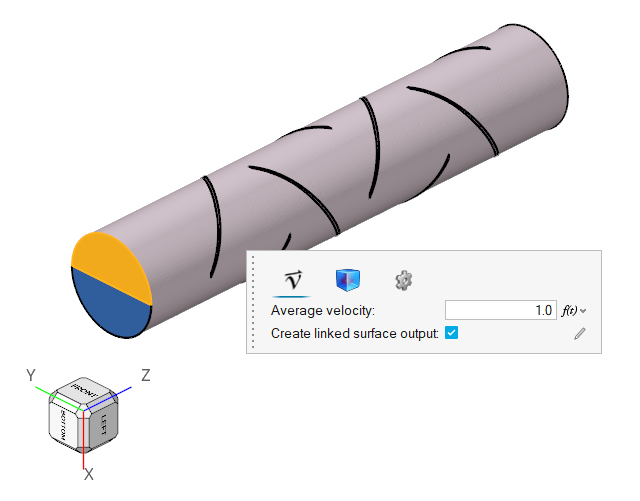
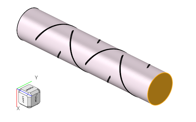
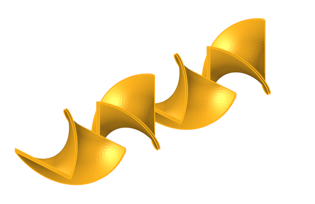
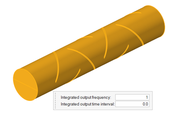
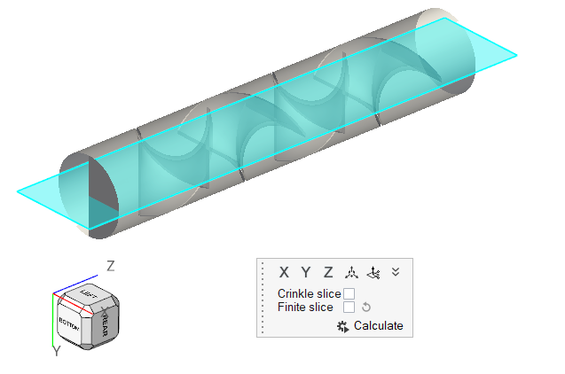
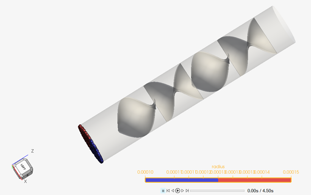
The problem to be addressed in this tutorial is shown schematically in Figure 1. It consists of a mixing tube that contains several swept walls to instigate mixing within the tube. The diameter of the inlet is 0.1 m and the length of the mixing tube is 0.525 m. The fins have a mean diameter of 0.1 m. The maximum thickness of the fins is 0.003 m.

Figure 1.
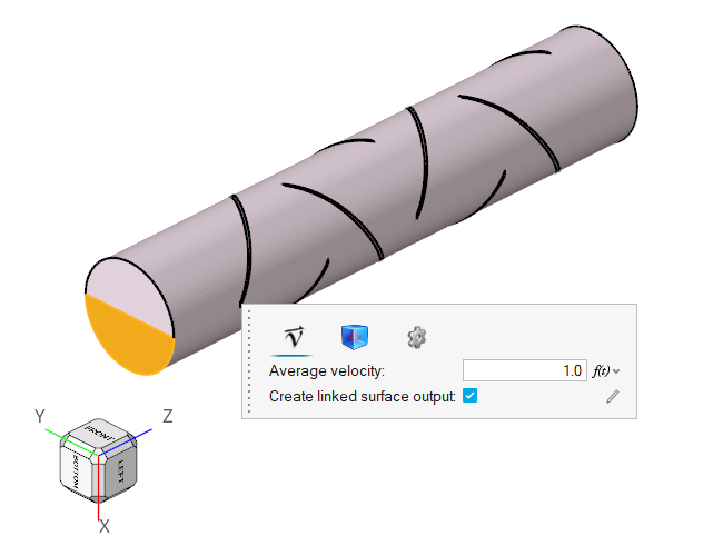
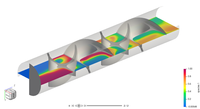
The boundary condition at the inlet is defined to produce a fully developed inlet profile with velocity of 1.0 m/s. One portion of the inlet is defined to contain 100 percent of species_1, while the other inlet is defined to contain 0.0 percent of species_1.
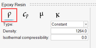
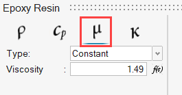
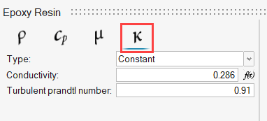
The fluid in this problem is an epoxy resin, which has a density of 1264.0 kg/m3 and a viscosity of 1.49 kg/m-sec.
Start HyperMesh CFD and Open the HyperMesh Database
Validate the Geometry
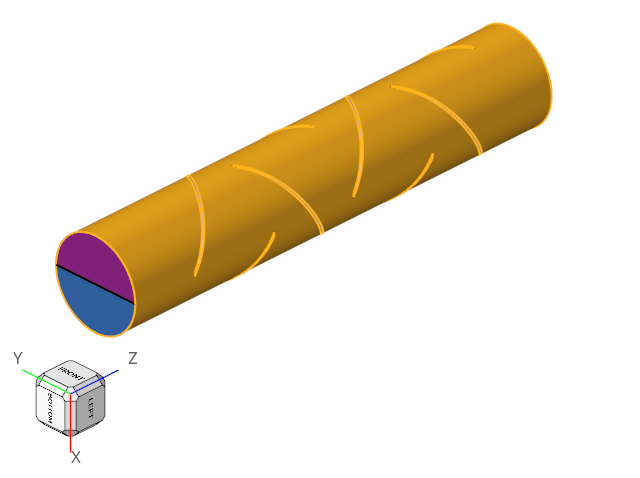
The Validate tool scans through the entire model, performs checks on the surfaces and solids, and flags any defects in the geometry, such as free edges, closed shells, intersections, duplicates, and slivers.

Figure 3.


