ACU-T: 6104 AcuSolve - EDEM Bidirectional Coupling with Non-Spherical Particles
This tutorial introduces you to the workflow for setting up and running a basic bidirectional coupling (two-way) simulation with non-spherical particles using AcuSolve and EDEM. Prior to starting this tutorial, you should have already run through the introductory tutorial, ACU-T: 1000 Basic Flow Set Up, and have a basic understanding of HyperMesh CFD, AcuSolve, and EDEM. To run this simulation, you will need access to a licensed version of HyperMesh CFD, AcuSolve, and EDEM.
Problem Description
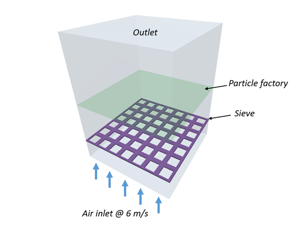
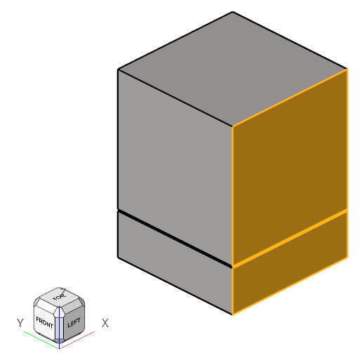
Figure 1.
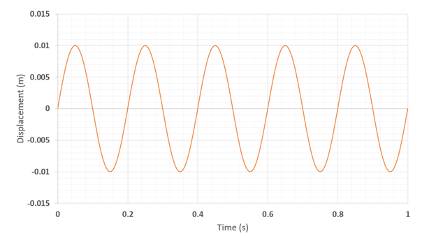
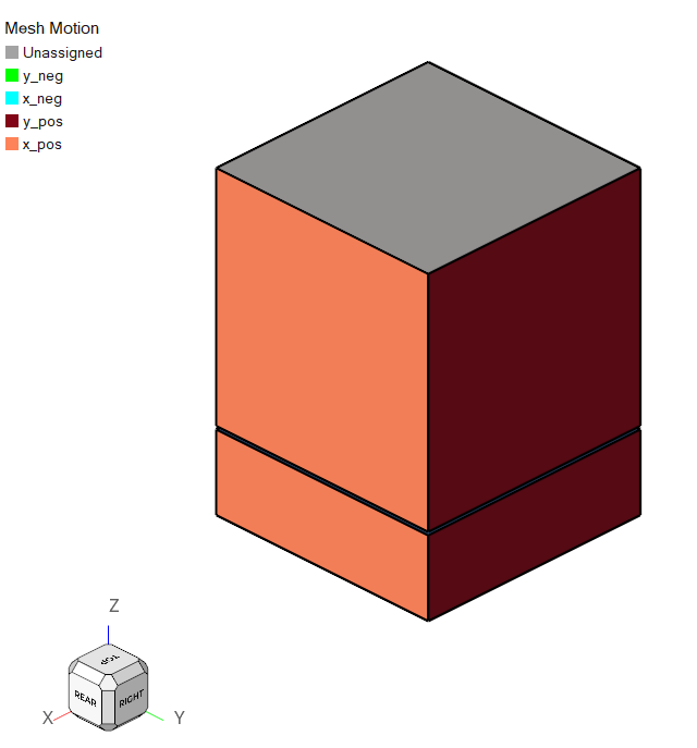
Figure 2.
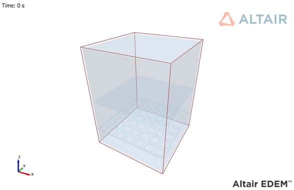
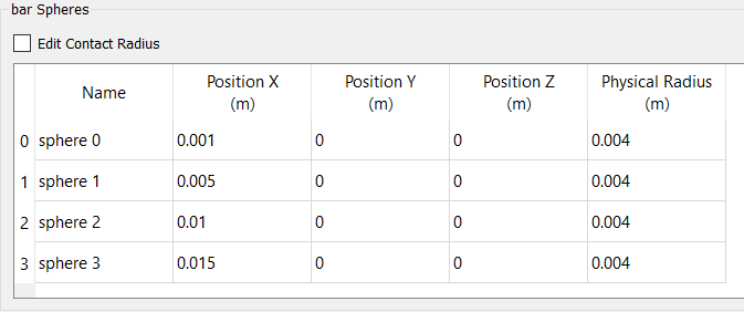
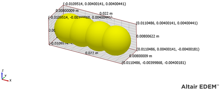
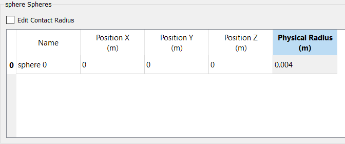
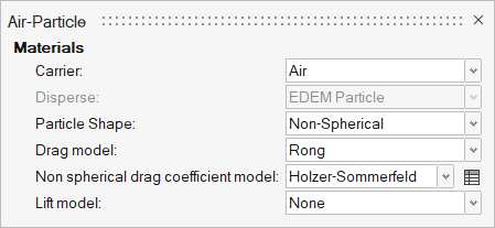
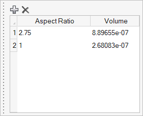
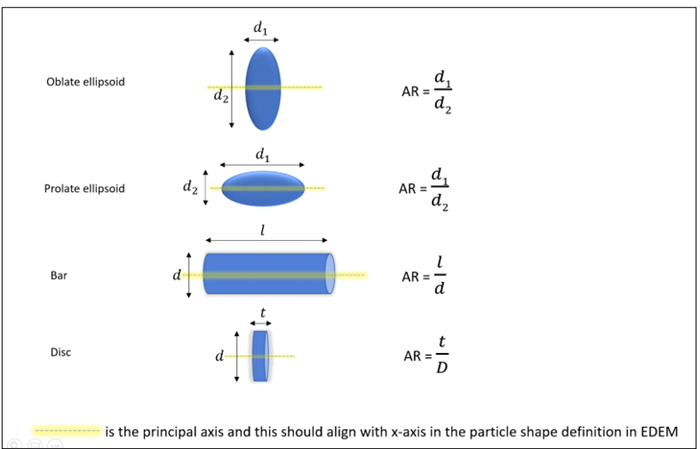
AcuSolve-EDEM bidirectional coupling is used to model the interaction between the fluid and particles. In this tutorial, non-spherical drag force models are used to accurately predict the drag forces on the particles by taking the shape of particles into consideration. The length scale used for factoring in the shape of the particles is the aspect ratio. Bar shaped particles with an aspect ratio of 2.75 and spherical particles with aspect ratio 1 are used for this simulation. The Rong drag model is used in conjunction with the Holzer-Sommerfeld non-spherical drag coefficient model.
| Particle Type | Density (kg/m3) | Size (m) | Number of particles |
|---|---|---|---|
| Bar | 200 | 0.022/0.008 (L/D) | 100 |
| Sphere | 1500 | 0.008 (D) | 200 |
- Isometric – where orientation of the particle is not considered in the drag force calculation. This model is applicable for shapes such as rocks, certain beans and ore particles. The Haider Levenspiel drag model is available for such scenarios and it requires particle’s sphericity and volume as inputs.
- Non-spherical – the orientation of the particle is considered for the drag force calculation. This option is applicable for shapes such as disc, plate and cylinder where the orientation of the particle with respect to the flow velocity influences the magnitude and direction of the force. Two options are available for such cases: Ganser and Holzer-Sommerfeld models. Both models require aspect ratio and volume of particles as inputs.
Part 1 - EDEM Simulation
Start Altair EDEM from the Windows start menu by clicking .
Open the EDEM Input Deck
Define the Bulk Materials and Equipment Material
In this step, you will define the material models for the bar and sphere-shaped particles.
Define Geometries and Factories
Define the Environment
In this step, you will define the extents of the domain for the EDEM simulation and the direction of gravitational acceleration.
Define the Simulation Settings
Part 2 - AcuSolve Simulation
Start HyperMesh CFD and Open the HyperMesh Database
Validate the Geometry
The Validate tool scans through the entire model, performs checks on the surfaces and solids, and flags any defects in the geometry, such as free edges, closed shells, intersections, duplicates, and slivers.

Figure 18.
Set Up Flow
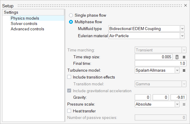
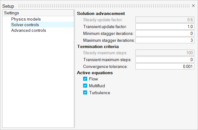
Set the General Simulation Parameters
Assign Material Properties
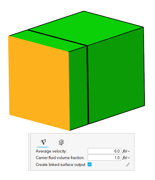
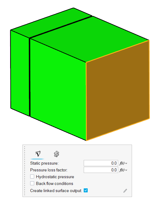
Define Flow Boundary Conditions
Set Up Motion
Select the Motion Type
Define the Mesh Boundary Conditions
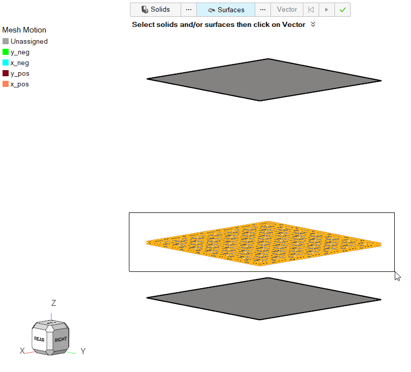
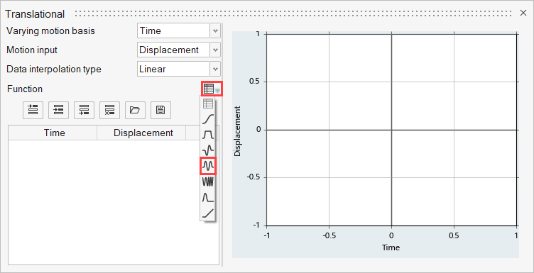
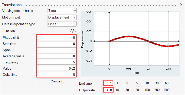
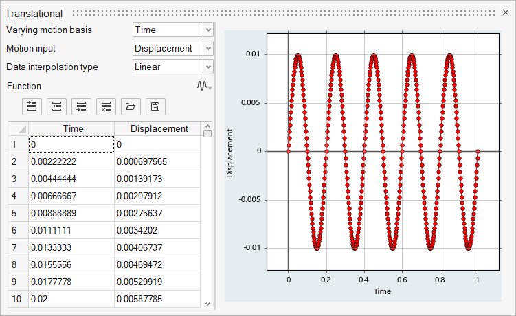
Define Sinusoidal Translational Motion
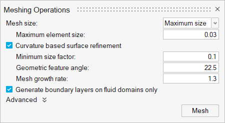
Generate the Mesh
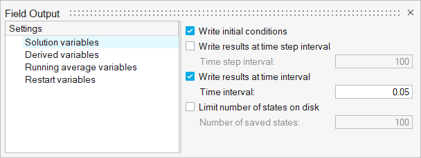
Define Nodal Outputs
Once the meshing is complete, you are automatically taken to the Solution ribbon.
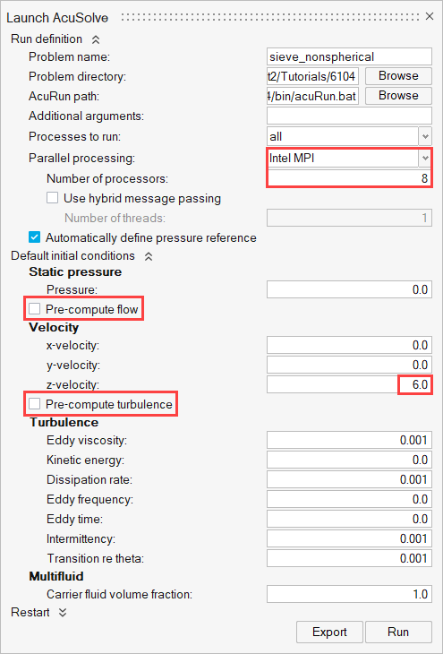
Submit the Coupled Simulation
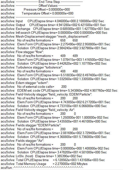
Analyze the Results
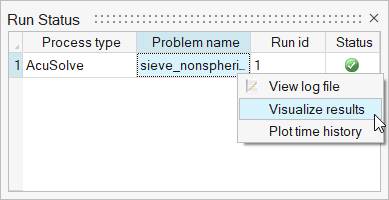
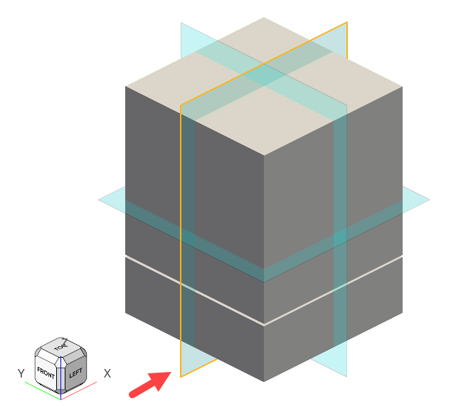
AcuSolve Post-Processing
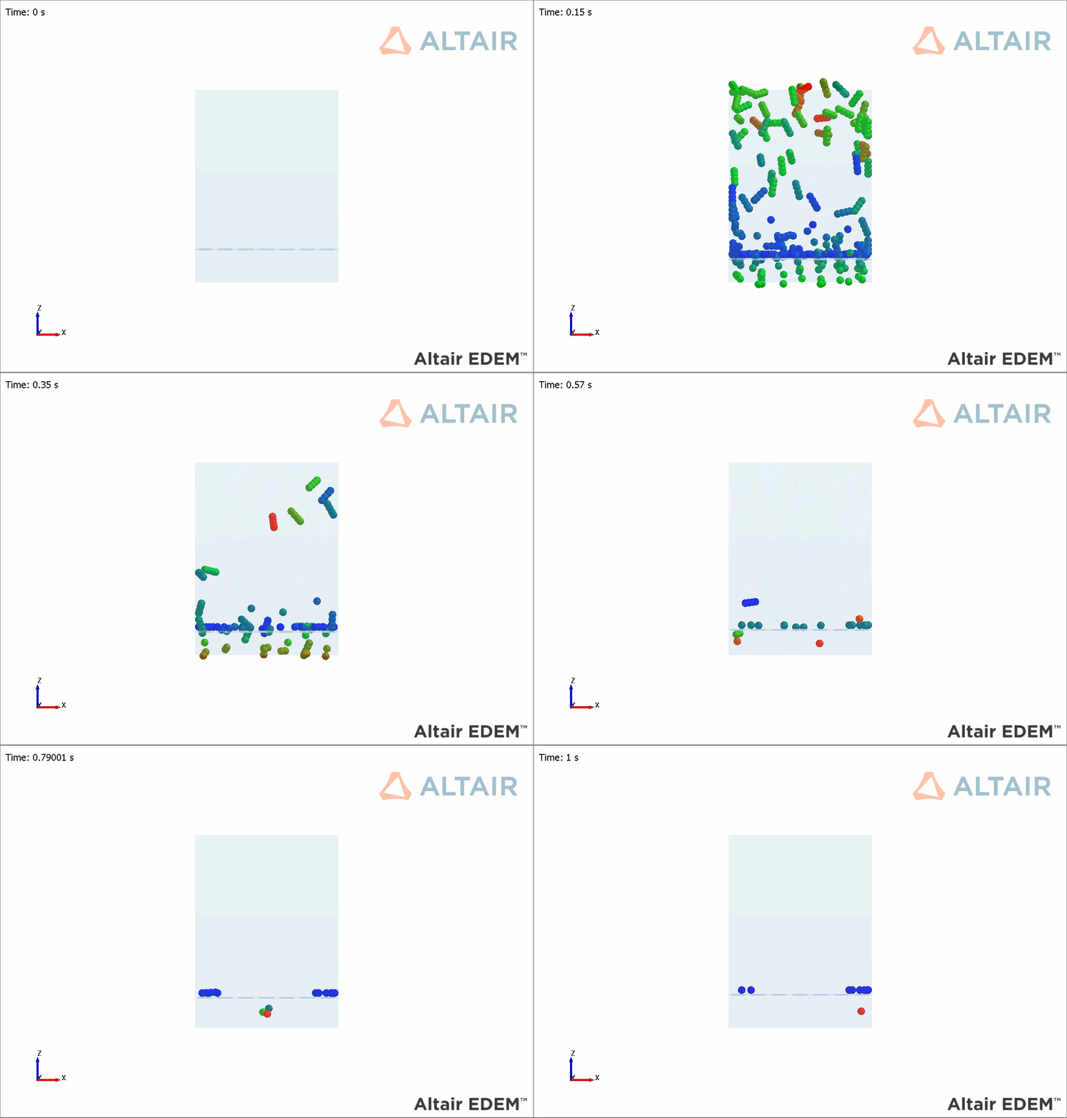
EDEM Post-Processing
Summary
In this tutorial, you learned how to set up and run a basic AcuSolve-EDEM bidirectional (two-way) coupling problem with non-spherical particles. You learned how to create a non-spherical particle in EDEM and set up the AcuSolve model to consider the effect of the particle shape for the fluid-particle interaction forces. Once the simulation was complete, you learned how to post-process the AcuSolve results using HyperMesh CFD and the EDEM results.
