Manage Scenarios
Scenarios are a mechanism to apply controls to engineering entities.
The Scenario Manager allows you to define a scenario with a name and solver profile. Within the scenario, you can then create a series of definitions comprised of rules and corresponding controls in a specific order. The order of the definitions determines how the controls are applied.
When applied, the scenario evaluates the rules in the order defined. If an engineering entity successfully meets the rule requirement, it has a control applied. Any engineering entity that doesn’t meet the rule requirement is moved to the next definition for evaluation. If any engineering entity successfully has a control applied, it is excluded from any later definition.
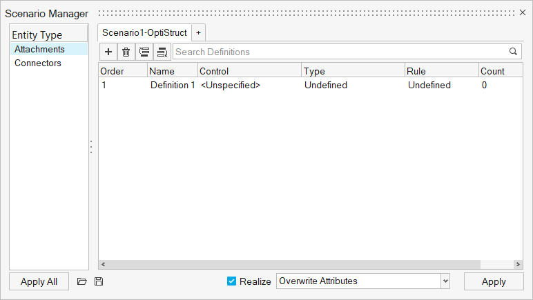
Figure 1.
-
From the Assembly ribbon, click the
Scenario tool.

Figure 2.Upon opening the Scenario Manager, an initial scenario is already available. - Optional:
Right-click on a scenario to duplicate, rename, change the solver interface, or
delete.
The solver interface filters the available controls. This ensures that the scenario is in a single solver.
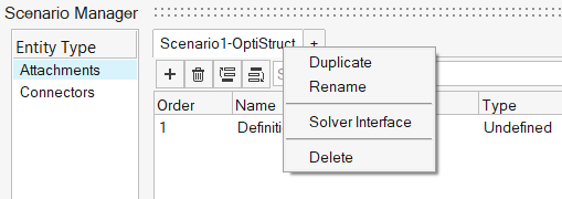
Figure 3.Click to create additional scenarios.
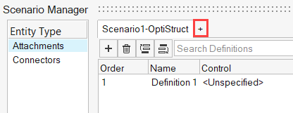
Figure 4. -
Click in the active scenario tab to create new definitions.
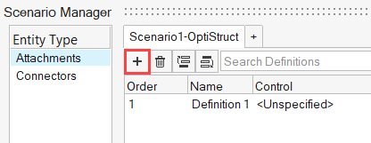
Figure 5.Similar to scenarios, right-click on a definition to rename, review, control the display, and delete.
-
Right-click on Rule column and select
Edit. Use the Rule Builder to
dynamically determine which engineering entities that a given control is applied
to.
The rule can be created based on Data on the engineering entity, by Shapes, by Selection, or All.
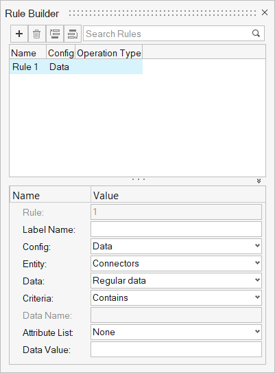
Figure 6. -
Click
 /
/ to reorder the definitions so they will be
evaluated in a different sequence.
to reorder the definitions so they will be
evaluated in a different sequence.
Controls, Engineering Entities, Attachments, Connectors