Browsers provide a structured view of model data, which you can use to review, modify, create, and manage
the contents of a model. In addition to visualization, browsers offer features like search, filtering, and sorting,
which enhance your ability to navigate and interact with the model data.
FE geometry is topology on top of mesh, meaning CAD and mesh exist as a single entity. The purpose of FE geometry
is to add vertices, edges, surfaces, and solids on FE models which have no CAD geometry.
Use the Model Checker to configure solver validity checks, modify and create new checks and corrections,
and fix modeling issues in an automatic or manual way.
Tools and workflows that are dedicated to rapidly creating new parts for specific use cases, or amending existing
parts. The current capabilities are focused on stiffening parts.
Use PhysicsAI to build fast predictive models from CAE data. PhysicsAI can be trained on data with any physics or
remeshing and without design variables.
Explore, organize and manage your personal data, collaborate in teams, and connect to other data sources, such as
corporate PLM systems to access CAD data or publish simulation data.
Use the Edges tool to find free edges and "T" connections in a group of shell
elements and create1D elements from them.
Free edges are defined as a pair of
nodes identifying an element edge that are not shared with another element. Free edges
are normally found around the outer perimeter of a part or around openings within the
part. Free edges found in your model are displayed as red plot elements in their own
component called ^edges.
Free edges within a field of elements typically indicate a
discontinuity within the mesh. Such discontinuities may be intentional, such as
crack modeling for durability simulation, or unintentional, due to geometry
discontinuities, meshing methods or component boundaries. In cases where the mesh
has a discontinuity, there will typically be more than one node at approximately the
same location in space. Such nodes are called "coincident".
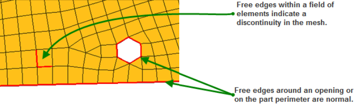
Figure 1.
From the Validate ribbon, click the
Edges tool.
Figure 2.
Optional: Click and define
additional options.
For Find, choose between finding free edges or T-connections.
Choose between creating plot elements or lines.
Select Smooth to create smooth (curved) lines
rather than jointed lines.
Restriction: Only available when creating lines.
For Break angle, specify the value above which a line will be broken
into two lines with a joint between them.
Restriction: Only available when creating lines.
From the guide bar, select an entity type.
In the modeling window, select the entities whose
associated edges you wish to find.
Optional: Preview free edges.
From the guide bar, click
Review.
Use the arrows on the guide bar to navigate
between found edges.
Complete one of the following options:
Click to find edges and create 1Ds
or lines.
Click to find edges and create 1Ds
or lines and exit the tool.
Click to exit the tool without
finding edges and creating 1Ds or lines.