/MAT/LAW117
Block Format Keyword This law represents the constitutive relation of ductile adhesive materials in 2 modes for normal and tangential directions. This law models the elastic and failure response of the material.
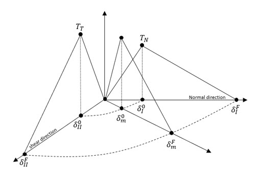
Figure 1. Representative scheme of the mixed mode model
Format
| (1) | (2) | (3) | (4) | (5) | (6) | (7) | (8) | (9) | (10) |
|---|---|---|---|---|---|---|---|---|---|
| /MAT/LAW117/mat_ID/unit_ID | |||||||||
| mat_title | |||||||||
| EN | ET | Imass | Idel | Irupt | |||||
| Fct_TN | Fct_TT | TN | TT | Fscale_x | |||||
| GIC | GIIC | EXP_B | EXP_BK | Gamma | |||||
Definition
| Field | Contents | SI Unit Example |
|---|---|---|
| mat_ID | Material identifier. (Integer, maximum 10 digits) |
|
| unit_ID | (Optional) Unit Identifier. (Integer, maximum 10 digits) |
|
| mat_title | Material title. (Character, maximum 100 characters) |
|
| Initial density. (Real) |
||
| EN | Stiffness normal to the plane of the cohesive
element. (Real) |
|
| ET | Stiffness in the plane of the cohesive
element. (Real) |
|
| Imass | Mass calculation flag.
(Integer) |
|
| Idel | Failure flag indicating the number of
integration points to delete the element (between 1 and
4). Default = 1 (Integer) |
|
| Irupt | Mixed mode displacement law flag.
(Real) |
|
| Fct_TN | Function identifier of the peak traction in
normal direction versus element mesh
size. (Integer) |
|
| Fct_TT | Function identifier of the peak traction in
tangential direction versus element mesh
size. (Integer) |
|
| TN | Peak traction in normal direction (default =
0) or, Fct_TN ordinate scale factor (default = 1) (Real) |
|
| TT | Peak traction in tangential direction (default =
0) or, Fct_TT ordinate scale factor (default = 1) (Real) |
|
| Fscale_x | Fct_TN and
Fct_TT abscissa scale factor. Default = 1 (Real) |
|
| GIC | Energy release rate for mode I. (Real) |
|
| GIIC | Energy release rate for mode II. (Real) |
|
| EXP_B | Power law exponent for the mixed mode. Default = 2 (Real) |
|
| EXP_BK | Benzeggage-Kenane exponent for the mixed
mode. (Real) |
|
| Gamma | Gamma exponent for Benzeggage-Kenane
law. Default = 1 (Real) |
Example (Connect Material)
#---1----|----2----|----3----|----4----|----5----|----6----|----7----|----8----|----9----|---10----|
/UNIT/1
Units
                  kg                  mm                  ms
#---1----|----2----|----3----|----4----|----5----|----6----|----7----|----8----|----9----|---10----|
/MAT/LAW117/1/1
CONNECT MATERIAL
#              RHO_I
              7.8E-6
#                 EN                  ET     Imass      Idel     Irupt
                   5                 1.2         0         1         0
#   Fct_TN    Fct_TT                  TN                  TT            Fscale_x
         0         0                   2                 0.7                   0
#                GIC                GIIC               EXP_B              EXP_BK               Gamma
                   1                1.75                   2                   2                   1
#---1----|----2----|----3----|----4----|----5----|----6----|----7----|----8----|----9----|---10----|
#ENDDATA
/END
#---1----|----2----|----3----|----4----|----5----|----6----|----7----|----8----|----9----|---10----|
Comments
- Mode I refers to the normal direction and mode II refers to the shear direction. is the separation in normal direction equal to direction. is equal to the separation in tangential direction . The mixed mode displacement is referred to by .
- The damage initiation
displacement in mode I and mode II are respectively,
and
and for the mixed mode:
(1) With the mode mix .
- The maximum displacement at
failure
can be calculated using either a Power law
for
Irupt=1:
(2) or, a Benzeggage-Kenane law for Irupt =2:(3) - GIC and
GIIC are the energy release rates between the peak
traction and the maximum displacement for mode I and mode II, respectively.
and