Visualize Results
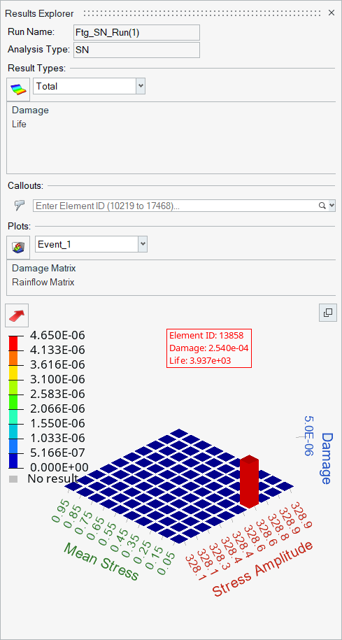
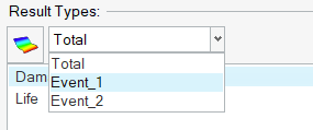
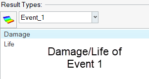
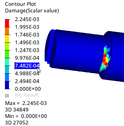
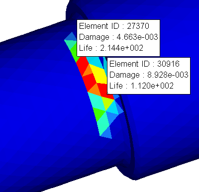
Use the Results Explorer to view plots and contours for various result types.
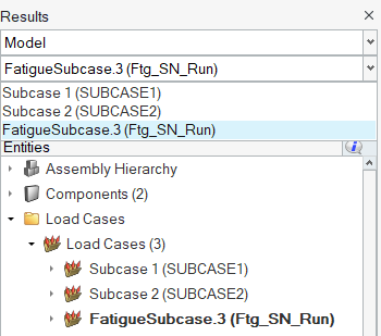
Figure 7.
Export Damage and Rainflow Matrix Data
The *.rfout file contains the rainflow cycle count for each fatigue event for the queried element highlighted in damage/rainflow matrix.
The total damage, which is the cumulative damage, is written at the end of all event details.
- Element ID
- The element ID in consideration.
- Event
- The ID of the fatigue event.
- Number of Cycles
- Number of rainflow cycles detected for the current element in the current fatigue event.
- Damage (besides event header)
- Damage in the fatigue event.
- Cycle
- Rainflow cycle ID.
- Stress Amplitude
- Stress amplitude of the current cycle.
- Mean Stress
- Mean stress of the current cycle.
- Damage
- Damage value of the current cycle.
- CorrectedStressAmp
- Corrected Stress Amplitude based on mean stress model selected.Note: Corrected Stress Amplitude output is only supported for Time Series and Transient Response type of loading.
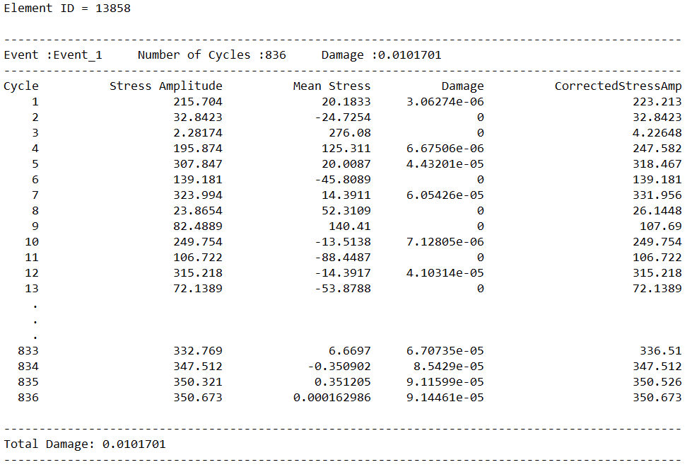
Figure 8.
- Element ID
- The element ID in consideration.
- Event
- The ID of the fatigue event.
- Number of Cycles
- Number of rainflow cycles detected for the current element in the current fatigue event.
- Damage (besides event header)
- Damage in the fatigue event.
- Cycle
- Rainflow cycle ID.
- Strain Amplitude
- Strain amplitude of the current cycle.
- Max Stress (SWT)
- Max stress of the current cycle.
- Mean Stress (MORROW)
- Mean stress of the current cycle.Note: Based on the mean stress model selected, one of the above columns (Max stress or Mean Stress) will be available in the rainflow matrix.
- Damage
- Damage value of the current cycle.
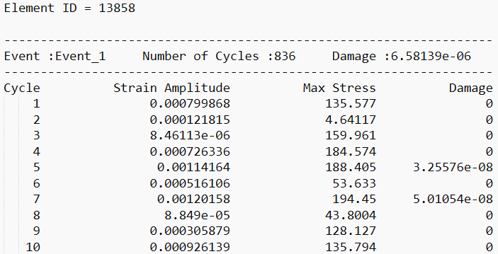
Figure 9.
- Element ID
- The element ID in consideration.
- Event
- The ID of the fatigue event.
- Number of Cycles
- Number of rainflow cycles detected for the current element in the current fatigue event.
- Damage (besides event header)
- Damage in the fatigue event.
- Damage Model
- Damage model being used for this cycle. Additionally, it also lists the critical plane determined to have the maximum damage (possible planes are T0, A0, A45, B45).
- Cycle
- Rainflow cycle ID.
- Normal Stress Amplitude
- Stress amplitude of normal stress for the current cycle (Goodman).
- Mean Stress
- Mean stress of the current cycle (Goodman).
- Shear Stress Amplitude
- Stress amplitude for the current cycle (Findley).
- Normal Stress
- Normal stress of the current cycle (Findley).
- Damage
- Damage value of the current cycle.
- CorrectedStressAmp
- Corrected Stress Amplitude based on mean stress model selected.
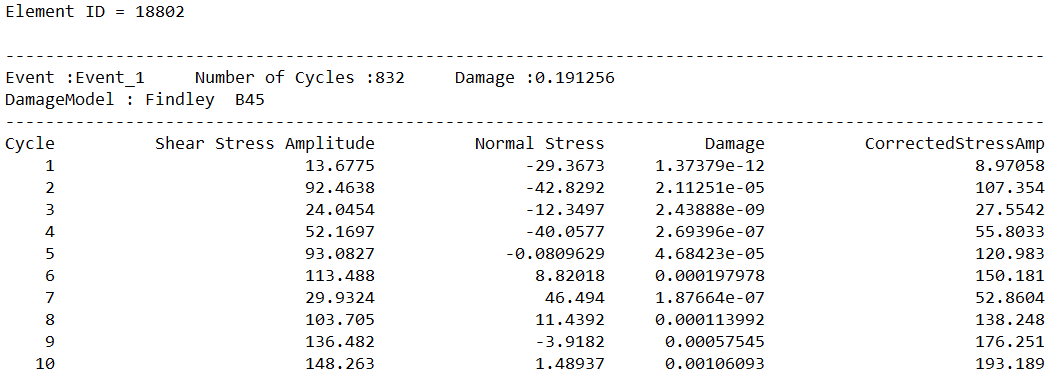
Figure 10. Findley Damage Model
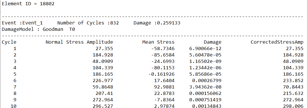
Figure 11. Goodman Damage Model
- Element ID
- The element ID in consideration.
- Event
- The ID of the fatigue event.
- Number of Cycles
- Number of rainflow cycles detected for the current element in the current fatigue event.
- Damage (besides event header)
- Damage in the fatigue event.
- Damage Model
- Damage model being used for this cycle. Additionally, it also lists the critical plane determined to have the maximum damage (possible planes are T0, A0, A45, B45).
- Cycle
- Rainflow cycle ID.
- Normal Strain Amplitude
- Strain amplitude of normal strain for the current cycle (SWT).
- Max Normal Stress
- Mean stress of the current cycle (SWT)
- Shear Strain Amplitude
- Strain amplitude for the current cycle (FS).
- Normal Stress
- Normal stress of the current cycle (FS).
- Shear Strain Amplitude
- Strain amplitude for the current cycle (BM).
- Mean Stress
- Mean stress of the current cycle (BM).
- Damage
- Damage value of the current cycle.
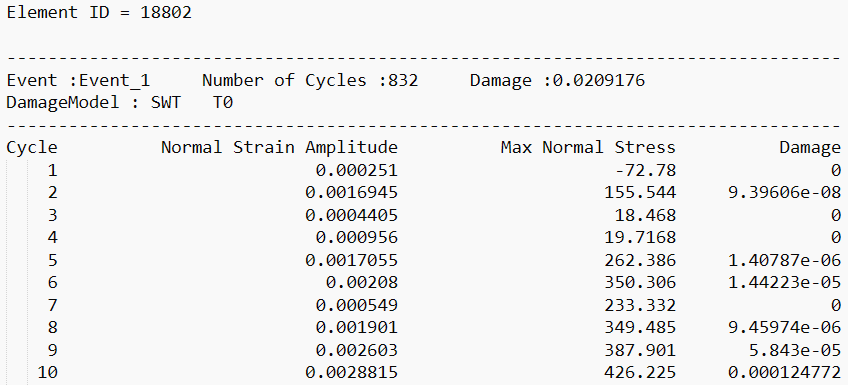
Figure 12. SWT Damage Model
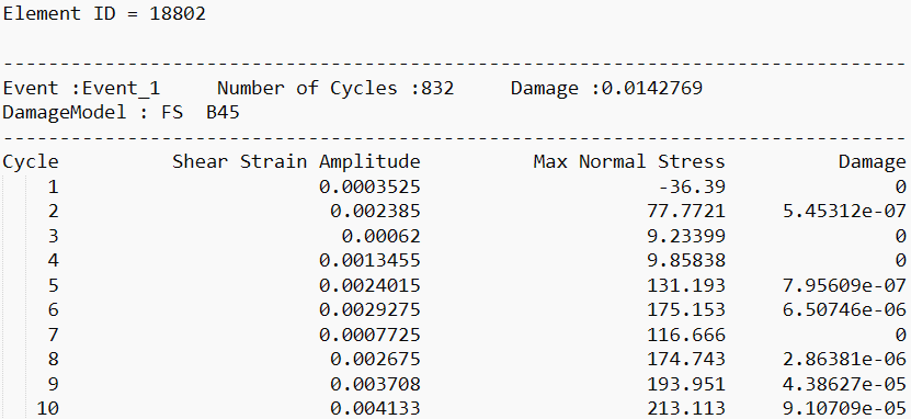
Figure 13. FS Damage Model
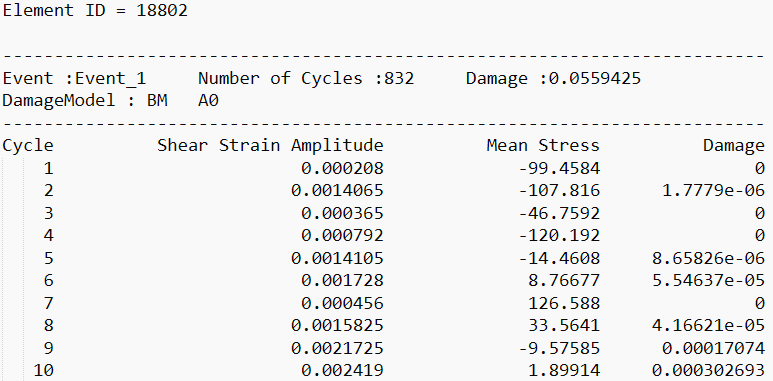
Figure 14. BM Damage Model
- Element ID
- The element ID in consideration.
- Event
- The ID of the fatigue event.
- Stress Amplitudes
- Number of stress amplitudes in the Random Response fatigue analysis for the current subcase.
- Damage (besides event header)
- Total damage in the event.
- Damage Model
- Random Response damage model used.
- Stress ID
- Rainflow cycle ID.
- Number of Cycles
- Number of cycles of the particular stress amplitude.
- Probability
- Probability of occurrence of the corresponding stress amplitude.
- Stress Amplitude
- Magnitude of stress amplitude.
- Mean Stress
- Magnitude of mean stress.
- Damage
- Cumulative damage value of all cycles at the current stress amplitude.
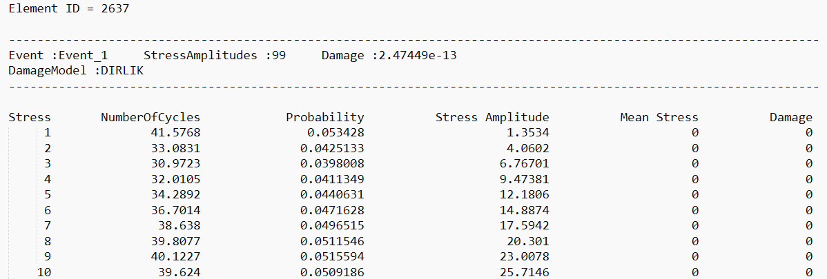
Figure 15.
- Element ID
- The element ID in consideration.
- Event
- The ID of the fatigue event.
- Frequencies
- Number of frequencies in the Sine Sweep fatigue analysis for the current subcase.
- Damage (besides event header)
- Total damage in the event.
- Freq
- Number/ID of the current frequency of interest.
- Number of Cycles
- Number of cycles of the particular frequency of interest.
- Stress Amplitude
- Magnitude of stress amplitude.
- Mean Stress
- Magnitude of mean stress.
- Damage
- Cumulative damage value of all cycles at the current stress amplitude.

Figure 16.

