In the
Component Arrangement Plan Setting dialog, the Global
section contains the following sections.
Default Reference Draw Option: Set the default reference area for the Top and
Bottom sides.
Set Board Display.
Reference Designator: Select whether to display the component.
Pin: Select whether to display the component pin (pad).
Pattern: Select whether to display the route.
Silk: Select whether to display the silkscreen.
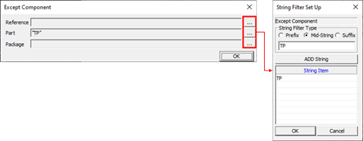
Except Component: Set the component that excludes from the display by
using the string filter.
Figure 1.
In the example above, the component that includes TP in the part
name is excluded.
Set Pin Display.
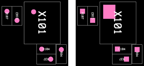
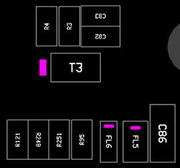
First Pin: Mark the first pin position.
First Pin-Pad Max Area: The first pin pad is marked with a pink solid
rectangle. If not selected, it displays as shown in Figure 2.
Figure 2.
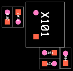
Second Pin: Mark the second pin location.
Figure 3.
Pin PAD Scale: Set the marking size of the first and second pins.
Fit Text to Area: Display the positions of pin number one and two
inside of the text area. This option only works for the two-pin
part.
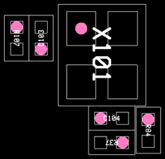
Pin MaxMin: Display the pad area as a rectangle shape.
Figure 4.
Polarity: Display the polarity mark for the polarized parts which can
be set in the Polarity item. For more information, see CAP Data Setting - Polarity.
Figure 5.
Set Name and Property Display.
Reference Name: Select whether to display the reference name.
Part Name: Select whether to display the part name.
Property Selection: Select whether to display the property
information.
Part Comment: Select a part property to display.
Reference Comment: Select a reference property to display.
Set Default Text Option.
Maximum Text Size: Display at the maximum size in the test area.
Display Text Area: Display the text area as a rectangle shape.
Text area definition: Define the text area as a pad or COC area.
Default Text Height: Set the text size. It will not exceed the text
area.
User Comp Data: Select whether to display the user comp data set in Other
menu.
User Comment: Select whether to display the user comment setting in Other
menu.
Upright Reading: Display the text direction according to the ratio of the text
area. If the proportion of the text area is larger in the horizontal direction,
the text displays in the left to right direction. In case of a large vertical
direction, the text displays from bottom to top.
Mechanical Component (No Pin): Select whether to display the parts without pin
information such as a fiducial mark or a screw hole.
Auto Zoom: Automatic zoom-in on the target part when you select a part in the
reference list.
Display CAP Setting File Name to PDF: Export the Component Arrangement Plan
setting file name when printing a PDF file.
Display CAD file created date to PDF: Export the current ECAD design file
creation date when printing a PDF file.
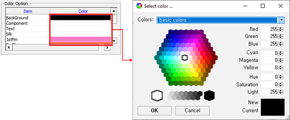
Color Option: Define the color of each item.
Figure 6.
Tool Option
Reference List: Select whether to display the reference list dialog on
the right side of the screen.
Display Option: Select whether to display the display option dialog on
the right side of the screen.
Label Display: Select whether to display the label on the upper right
side of the screen.
Label Title: A list of labels that appear on the label. You can edit
the title by clicking add or
delete.
Layer Option
Top Layer: When displaying the top side, select the artwork layer to
display.
Bottom Layer: When displaying the bottom side, select the artwork layer
to display.
Display Text on Selected Layer to PDF: Include the part’s text of the
selected artwork layer when printing a PDF.
EBOM Link Option: Specify the *.ebi file set in PollEx BOM. Refer to the PollEx BOM
manual for how to create the *.ebi file.
Export boundary to PDF: Specify the PDF export area.
PCB Outline: Export based on the PCB outline area.
Component: Export including the part area placed on the PCB.
Board Figure (Drill): Export including the figure object area placed on
the PCB.