Use the Edit Beam: Align tool to reorder the N1 to N2 sequence of 1D element
nodes.
This tool allows you to reorder element nodes using a vector or a system axis.
In this optional step, you can select elements in order to reorder N1 & N2 in
ascending order along one or multiple axes if elements are aligned with such
vector(s) in a given angle tolerance.
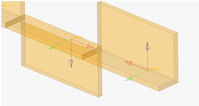
This is typically useful when beam section shape is not symmetric. Figure 1.
From the 1D ribbon, click the Edit Beam > Align tool.
Figure 2.
Select elements to align.
Activate the System selector on
the guide bar then select a system to use local reference
axes.
By default, the global system is used.
Define a reference axis to align with.
The vector formed by beam nodes N1->N2, is compared to reference vector. If
the angle between the 2 vectors is below the angle tolerance, then directions
are considered as matching. Matching elements will have N1 and N2 ordered along
the positive direction of reference vector.
Use the icon drop-down menu on the left of the microdialog to select whether the direction is
defined as an arbitrary vector or a system axis.
If you selected "by axis", select the (multiple) system axes for
sorting beams within the given tolerance.
If "by vector”, click to invoke the Vector tool, define the reference vector, then click Esc to return to the Align
context.
Picking an element when the Vector tool is
active will consider this element as a reference element and align the
selection from the X axis of the reference element. Figure 3.
Change the angle tolerance.
Values greater than 60 degrees are reset to 60 degrees.
Alternatively, to simply reverse the orientation of your selection,
click .
On the guide bar, click one of the following:
- Save changes and stay in the tool
- Save changes and close the tool
Tip: Use the legend in the top-left of the modeling window to plot the axes of the elemental systems.

 to invoke the Vector tool, define the reference vector, then click Esc to return to the Align
context.
Picking an element when the Vector tool is active will consider this element as a reference element and align the selection from the X axis of the reference element.
to invoke the Vector tool, define the reference vector, then click Esc to return to the Align
context.
Picking an element when the Vector tool is active will consider this element as a reference element and align the selection from the X axis of the reference element.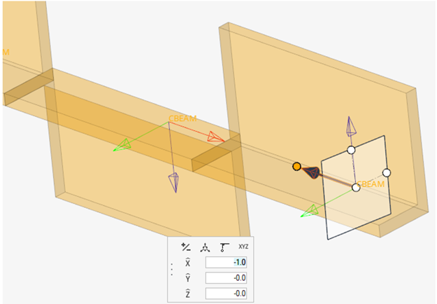
 .
.
 - Save changes and stay in the tool
 - Save changes and close the tool