Test-Point Location Generator is a software for generating test points and
extracting the location and data by referring to the design data.
Depending on the routing structure, this software provides versatile functions to
generate test point locations. Use this software to load a netlist used and modified
in manufacturing sites and to compare them with the original design data. Test-Point Location Generator is under the Manufacturer menu in PollEx PCB including three menus; Extract JIG Data, Result
Review, and Verify Netlist.
Launch PollEx PCB.
From the menu bar, click File > Open and open the PollEx_MFG_Sample_T2_r1.0.pdbb
file from:
C:\ProgramData\altair\PollEx\<version>\Examples\MFG\.
Refer to the PCB for how to use
the PollEx PCB viewer.
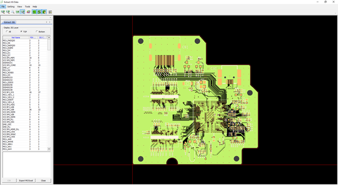
From the menu bar, click Manufacture > Test-Point Location Generator > Extract JIG Data.
From the menu bar, click Tools > Extract JIG Data.
The extracted JIG data are displayed on the left-side of the
Extract JIG Data dialog. Figure 1.
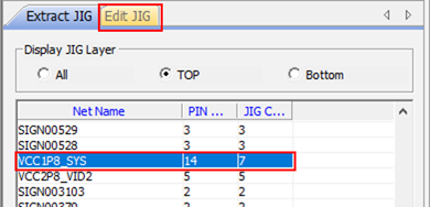
Edit JIG Data.
Select VCC1P8_SYS from the list.
The Edit JIG tab displays. Figure 2.
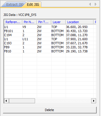
Click Edit.
The JIG data of the selected net is displayed.
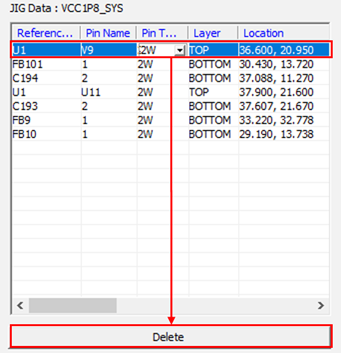
Click each Reference Name to zoom in on the JIG location.
Figure 3.
Click U1 and click Delete
to delete the JIG data from the list.
Figure 4.
In the toolbar, click .
The selected net is displayed in the window.
Note: must be activated to add the JIG
data. Figure 5.
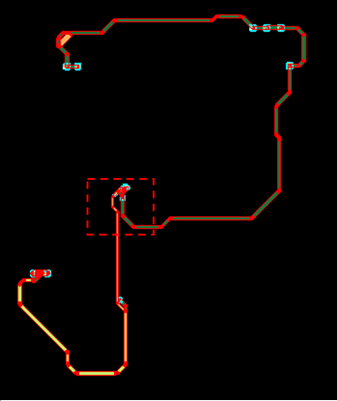
Click Add and click
C192.
The C192 is in the red-dotted area. Figure 6.
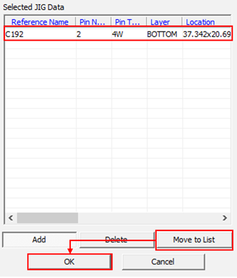
The selected JIG pin is added in the Selected JIG Data.
Click Move to List to apply the added JIG data
into the selected net and click OK.
Figure 7.
Verify Netlist.
In the toolbar, click .
From the menu bar, click Tools > Verify Netlist.
This menu is activated after the Extract JIG Data is executed.
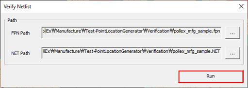
Click in the FPN Path row and select the
pollex_mfg_sample.fpn file in the following
directory:
C:\ProgramData\altair\PollEx\<version>\Examples\MFG\Test-PointLocationGenerator\Verification.
Click Open.
Click Run.
If the NET Path is not defined, select the same directory as the
*.FPN file. Figure 8.
The Verification Result is displayed in the tab.
Define distribution.
From the menu bar, click Tools > Distribution.
The Distribution dialog opens.
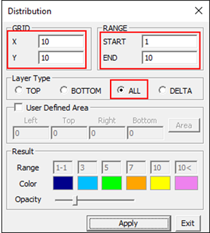
In the Distribution dialog, select
ALL for Layer Type and enter the following
GRID and Range values:
X = 10
Y = 10
START = 1
END = 10
Figure 9.
Click Apply.
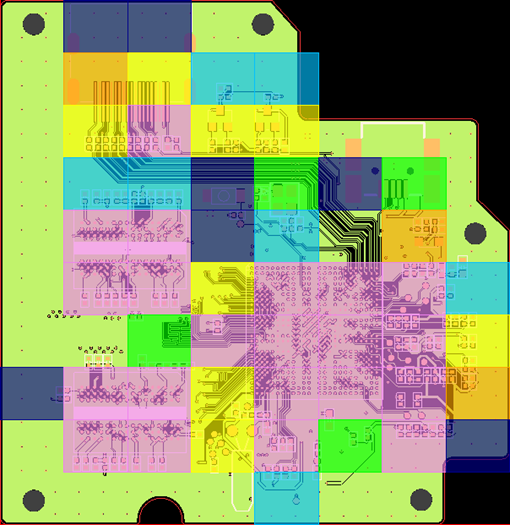
Check the distribution of the JIG data in the PDB design.
Figure 10.
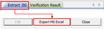
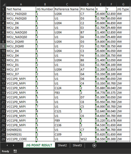
From the Extract JIG tab, click Export MS Excel to
export extract JIG data.
Figure 11. Figure 12.
From the menu bar, click Manufacture > Test-Point Location Generator > Result Review.
Set Result Data.
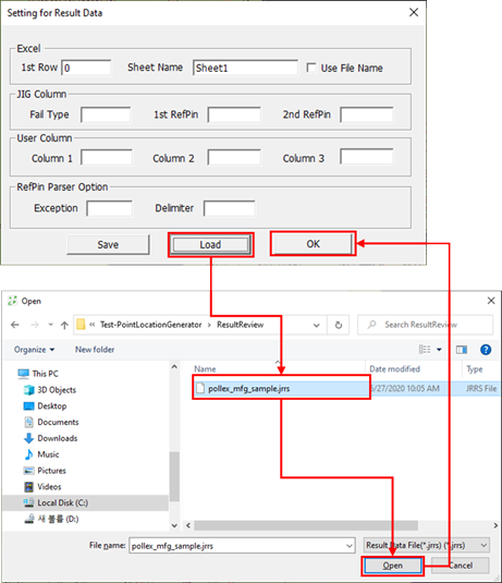
From the menu bar, click Setting > Setting for Result Data.
Click Load and select the
pollex_mfg_sample.jrrs file from the following
directory:
C:\ProgramData\altair\PollEx\<version>\Examples\MFG\Test-PointLocationGenerator\ResultReview.
Click Open and click OK.
Figure 13.
Open the Result Data.
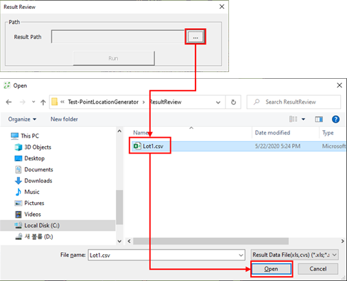
From the menu bar, click Tools > Result Review.
In the Result Review dialog, click to select the Lot1.csv
file.
Click Open.
Figure 14.
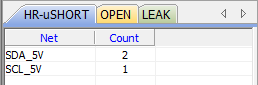
Click Run.
Each Fail Type defined in the Setting for Result Data is displayed in
each tab. Figure 15.
Open verify netlist.
This function is very similar to the function defined in step 6, but this provides
the comparison including JIG pins data. This menu does not require to run
Extract JIG Data before executing this menu.
From the menu bar, click Manufacture > Test-Point Location Generator > Verify Netlist.
From the menu bar, click Tools > Verify netlist.
Open files.
This step for opening *.FPN and
*.NET from the bare board tester is the same as
defined in step 6.
Review the verified results of the netlist in each tab.
 .
The selected net is displayed in the window.Note:
.
The selected net is displayed in the window.Note: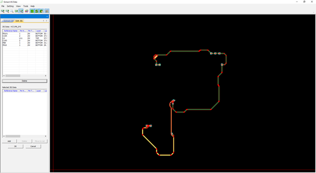
 in the FPN Path row and select the
pollex_mfg_sample.fpn file in the following
directory:
C:\ProgramData\altair\PollEx\<version>\Examples\MFG\Test-PointLocationGenerator\Verification.
in the FPN Path row and select the
pollex_mfg_sample.fpn file in the following
directory:
C:\ProgramData\altair\PollEx\<version>\Examples\MFG\Test-PointLocationGenerator\Verification.