Systems are required to satisfy multiple objectives. These problems require a
slightly different approach.
Multi-objective optimization may be stated as follows:
Minimize
(objective function)
Subject to
(inequality constraints)
(equality constraints)
(design limits)
The functions in the cost and constraint functions are assumed to
have the form:
In MotionSolve, a multi-objective problem is transformed to a
single-objective problem by redefining the cost function as follows:
Minimize:
(objective function)
Subject to:
(inequality constraints)
(equality constraints)
(design
limits)
are a set f weights that reflect the relative
importance of the various objectives.
Example 1
Design Goal
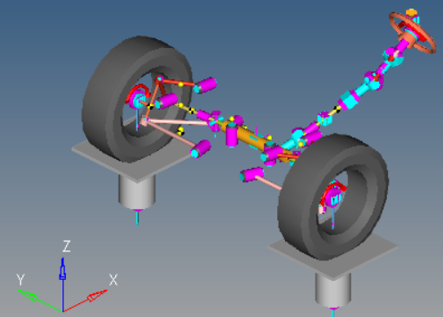
Considering a kinematic SLA suspension, the design goal is to modify
hard points in a suspension to obtain desired ride behavior.
Figure 1.
The ride behavior is characterized by six objectives:
Ride Steer @ Design = -4°/m
Ride Steer @ Full Jounce = -4°/m
Ride Camber @ Design = +5°/m
Ride Camber @ Full Jounce = +5°/m
Ride Caster @ Design = -8°/m
Ride Caster @ Full Jounce = -8°/m
Ride Steer =
Ride Camber =
Ride Caster =
Design Variables
Various hard point locations in the suspension are available as design
variables. For this problem, there are 26 design variables.
Upper Control Arm Inboard hard-points (Fore/Aft)
XYZ
(6 DV)
Lower Control Arm Inboard hard-points (Fore/Aft)
XYZ
(6 DV)
Upper Ball Joint hard-point XYZ
(3 DV)
Lower Ball Joint hard-point XYZ
(3 DV)
Tie rod Inner & Outer XYZ
(6 DV)
Spindle Alignment Point Location XZ
(3 DV)
Results
For this example, the optimization method worked quite well.
Response
Target
Actual
Ride Steer @ Design
-4 °/m
-4.107 °/m
Ride Steer @ Full Jounce
-4 °/m
-3.898 °/m
Ride Camber @ Design
+5 °/m
+4.937 °/m
Ride Camber @ Full Jounce
+5 °/m
+5.024 °/m
Ride Caster @ Design
-8 °/m
-8.402 °/m
Ride Caster @ Full Jounce
-8 °/m
-7.594 °/m
Example 2
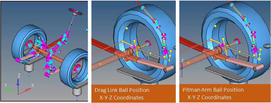
This is another suspension example for a bus. The task at hand is to design the
steering system to meet required metrics. In a properly design steering system:
The left and right wheels have zero steer when the steering wheel angle is
zero.
The steering angle difference between the left and right wheels should be
zero at maximum steer and minimum steer.
Steering ratio refers to the ratio between the turn of the steering wheel
and the turn of the wheels. The steering ratio at zero steering wheel angle
is required to be 9.27.
Figure 2.
The problem has four objectives:
Left Wheel Steer Angle @ zero Steering Wheel Angle =0
Right Steer Angle @ zero Steering Wheel Angle =0
Steer Angle Difference between left and right wheels = 0
Steering Ratio @ Zero Steering Wheel Angle = 9.27
Design Variables
Drag Link Ball Position X-Y-Z Coordinates
Pitman Arm Ball Position X-Y-Z Coordinates
Results
For this example, the optimization method worked quite well. The results
obtained are shown below: