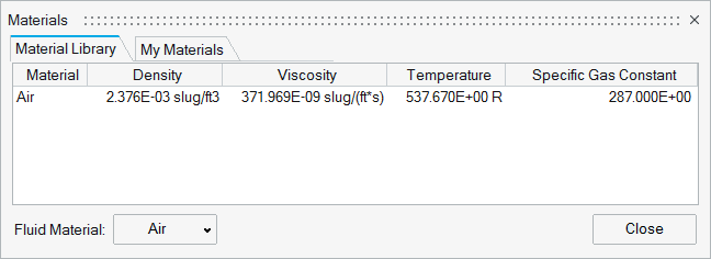
Define Fluid Materials
Use the Material tool to define a fluid material for the wind tunnel.
View new features for HyperMesh CFD 2023.1.
Learn the basics and discover the workspace.
Discover HyperMesh CFD functionality with interactive tutorials and community resources.
Solution-centric workflows allow you to traverse through modeling environments using a dedicated UI layer.
Create, open, import, and save models.
Use the Convert tool to convert entire models between data types.
Manage CAD, FE, and 2D parametric sketch geometry.
Generate surface/volume mesh by defining mesh controls, or interactively create and edit 2D surface mesh.
Prepare your model and run the simulation.
Prepare your model for a general AcuSolve simulation.
Prepare your model for wind tunnel analysis using ultraFluidX.
After preparing your model, use the Data Transfer tool to transfer mesh data to the environment used for aerodynamic and aeroacoustic setup.
Manage the parts and assemblies that make up your model.
Set up the wind tunnel and prepare the aerodynamics and parameters of your model.
You can change the unit system using the Unit System Selector or the Preferences. When importing "discrete mesh" files (.stl, .nas, .fem) with unspecified units, select the model unit in the Import Options dialog.
Use the Systems tool to define local coordinate systems and translate the parts needed to align the model.
Use the Edit Tunnel tool to define the size of the wind tunnel.
Use the Turbulence tool to generate turbulence source regions.
Use the Move tool to position the car inside of the wind tunnel.
Use the Identify Parts tool to define types of parts like wheels, heat exchangers or body panels, which require specific modeling techniques for the CFD run.
Baffles are used to model very thin walls, for example sheet metal parts. In the numerical surface mesh model, baffles are represented by shell elements, which have fluid volume on both sides.
By default, parts have Wall Model properties associated with it.
Use the Ride Height tool to adjust the heave, pitch, and roll of the model.
Use the Normals tool to identify and correct the surface normal directions on parts.
Use the Mesh Controls tool to define regions with a user-defined volume element size.
Use the Material tool to define a fluid material for the wind tunnel.
Use the Belt System tool to model a belt system.
Use the Output tool to create output controls.
Submit jobs and view reports.
Post-process the simulation results by creating visualizations and measurements.
Automate simulation processes with templates and utility scripts.
Once the baseline model is prepared, you can define morph volumes, morph geometry, create design shapes and run DOE studies. These tool work for both AcuSolve and ultraFluidX-based workflows.
More resources for AcuSolve and ultraFluidX solvers.
Prepare your model and run the simulation.
Prepare your model for wind tunnel analysis using ultraFluidX.
Set up the wind tunnel and prepare the aerodynamics and parameters of your model.
Use the Material tool to define a fluid material for the wind tunnel.
© 2023 Altair Engineering, Inc. All Rights Reserved.
Intellectual Property Rights Notice | Technical Support | Cookie Consent