OS-T: 1394 Axi-Symmetric Ball Joint
This tutorial demonstrates how to carry nonlinear analysis for Axi-symmetric ball joint for pull load of 10,000N using OptiStruct.
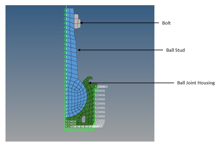
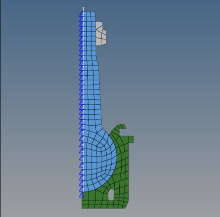
Figure 1. Model and Loading Description
- Set up the Ball Joint 2D axi symmetric analysis in HyperMesh
- Submit the job in OptiStruct
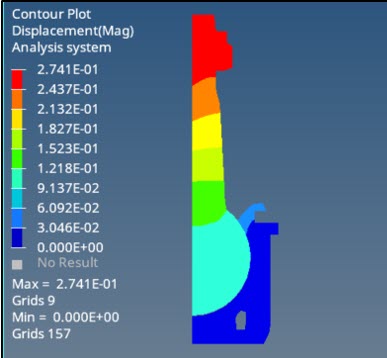
- View results in HyperView
Launch HyperMesh and Set the OptiStruct User Profile
Open the Model
Set Up the Model
Mesh the Model with CQAXI Elements
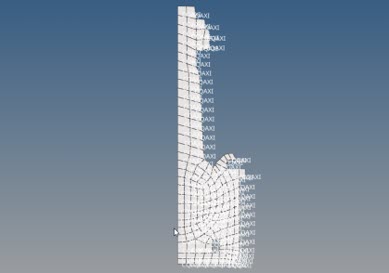
The meshed 2D part has CQUAD4 elements and for axisymmetric model CQAXI elements are used.
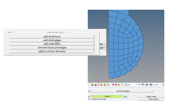
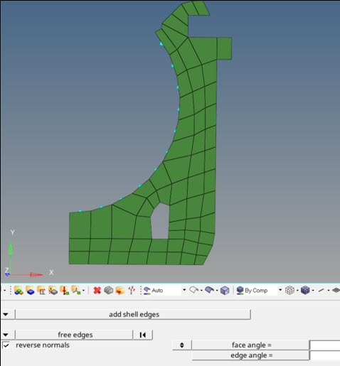
Create Set Segments
This step creates the main surface for the ball stud.
Create the Contacts
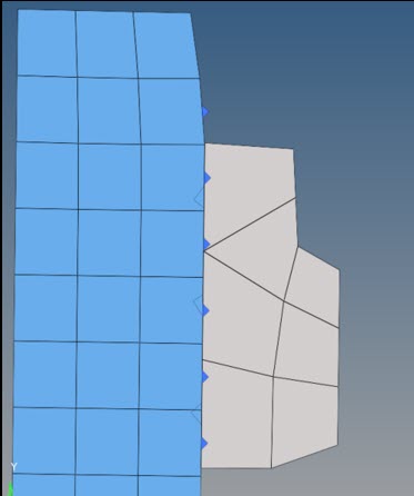
First, you will create the contact between ball stud and housing, then the contact between bolt and ball stud.
- In the Model Browser, right-click and select from the context menu.
- For Name, enter CONTACT1.
- For Property Option, select static coeffic friction in the Entity Editor.
- For MU1, enter 0.2.
- For SSID (Secondary), select set from the drop-down menu and select Secondary surface.
- For MSID (Main), select set from the drop-down menu and select main (set segment).
- In the Model Browser, right-click and select from the context menu.
- For Name, enter TIE.
- For Card Image, select TIE.
- For SSID (Secondary), select Secondary_bolt from the drop-down menu.
- For MSID (Main), select Main_ball_stud from the drop-down menu.
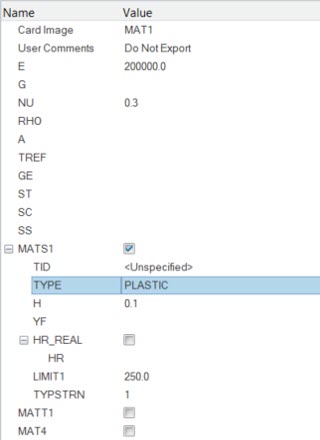
Create the Material
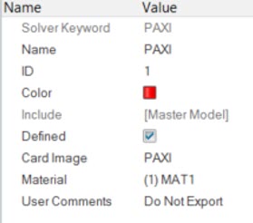
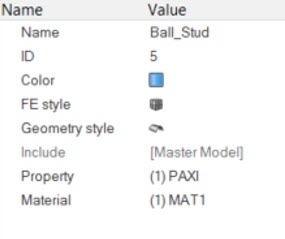
Create the Properties
Apply Loads and Boundary Conditions
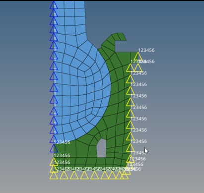
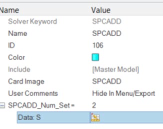
Create SPCs Load Collector
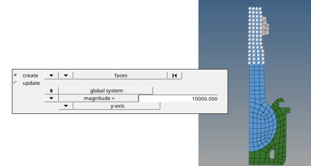
Create Force Load Collector
This step will outline how to apply the force.
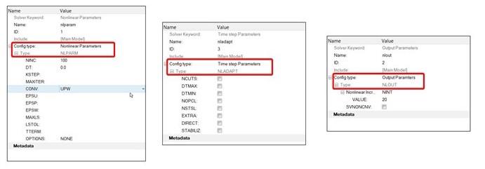
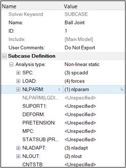
Create Load Steps
Define Output Control Parameters
- From the Analysis page, select control cards.
- Click on GLOBAL_OUTPUT_REQUEST.
- Below CONTF, DISPLACEMENT, STRAIN and STRESS, set Option to Yes.
- Click return twice to go to the main menu.

 (Contour).
 from the
panels window.