Generate Custom Refinement Zones

Create an arbitrary refinement zone around a closed volume.

This function is useful in cases where you want to have refinement in a specific shape to capture the flow, such as the wake of a side view mirror. If the part that is selected does not form a closed volume, the mesh within the bounding box of the part will be refined.

Create custom refinement zones in the following ways:

  • Use the Custom tool.
    1. From the Setup ribbon, click the Mesh Controls tool.


      Figure 1.
    2. From the secondary tool set, click the body of the Custom tool.


      Figure 2.
    3. Select a part.
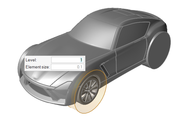
      A new refinement zone is generated and the selected part becomes transparent.
    4. Enter a value for Level in the microdialog.


      Figure 3.
      Note: All mesh controls in the model are defined relative to the far field size, and must be a power of 2 of the far field size. For example, if you define a far field mesh size of 1 m, the available refinement sizes will be 0.5, 0.25, 0.125, and so on.
  • Right-click on a part in the modeling window or the Model Browser and select Identify As > Custom Zone from the context menu.
  • Select a part in the modeling window or the Model Browser then change the Identify As field to Custom Zone in the Property Editor.
Tip: Modify the refinement zone's dimensions in the Property Editor.