MATBRT
Bulk Data Entry Defines the material properties for Brittle Damage material models.
Format
| (1) | (2) | (3) | (4) | (5) | (6) | (7) | (8) | (9) | (10) |
|---|---|---|---|---|---|---|---|---|---|
| MATBRT | MID | ||||||||
| CRACK | OPTION | ||||||||
| V1 | V2 | ||||||||
| etc. | etc. | ||||||||
| SHEAR | OPTION | ||||||||
| V3 | V4 | ||||||||
| etc. | etc. | ||||||||
| FAILURE | NDIR | ||||||||
| V5 | PFAIL |
Example
| (1) | (2) | (3) | (4) | (5) | (6) | (7) | (8) | (9) | (10) |
|---|---|---|---|---|---|---|---|---|---|
| MATBRT | 2 | ||||||||
| CRACK | ENER | ||||||||
| 250.0 | 0.4 |
Definitions
| Field | Contents | SI Unit Example |
|---|---|---|
| MID | Material identification
number. No default (Integer > 0) |
|
| CRACK | Flag indicating that parameters for tensile cracking behavior are to follow. 3 | |
| OPTION | The following options are
available for tensile crack behavior (Mode I):
|
|
| V1, V2 | Values of V1 and V2 depend on the OPTION chosen for tensile crack behavior. 3 |
for V1 for V2 if OPTION= DISP or ENER |
| SHEAR | Flag indicating that the parameters for shear cracking behavior are to follow. 4 | |
| OPTION | The following options are
available for shear crack behavior (Mode II):
|
|
| V3, V4 | Values of V3 and V4 depend on the OPTION chosen for shear crack behavior. 4 |
for V4 if OPTION= DISP or ENER |
| FAILURE | Flag indicating parameters for defining the limit of element deletion with the crack opening. | |
| NDIR | Number of directions that
should reach the critical crack opening value
(V5) before element deletion.
|
|
| V5 | If the
CRACK
OPTION=STRN, defines the value
of critical strain crack opening (
). If the CRACK OPTION=DISP or ENER, defines the value of critical displacement crack opening ( ) Default = blank (Real) |
for V5 if OPTION= DISP or ENER |
| PFAIL | Percentage of failed
integration points prior to element deletion. Default = 1.0 |
Comments
- MATBRT is currently supported only for explicit dynamic analysis (NLEXPL).
- A MATBRT entry should have the same MID as a MAT1 entry in the same model. The MAT1 entry is used to define the linear isotropic elastic behavior prior to crack initiation. The curves defined in the comments below define only the cracking behavior post crack initiation.
- For tensile crack, there is no
change to compression behavior and only tensile cracking is considered.
CRACK defines the tensile crack behavior (Mode I):
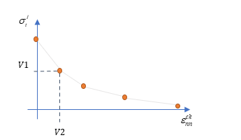
- STRN
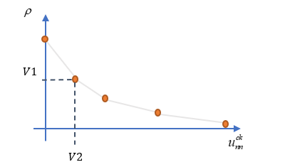
- Crack opening is expressed in the form of positive principal stress ( ) versus crack opening strain ( ). The series of values (V1, V2) define a table of ( , ).
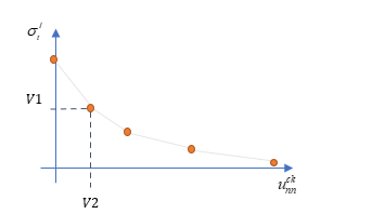
- DISP
- Crack opening is expressed in the form of positive principal stress ( ) versus crack opening displacement ( ). The series of values (V1, V2) define a table of ( , ).
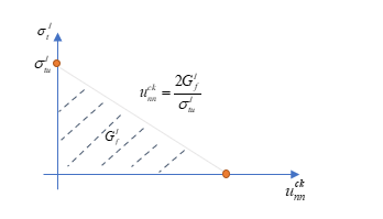
- ENER
- Crack opening is expressed in the form of positive principal stress ( ) and fracture energy ( ). The value of V1 is and V2 is .
- For shear crack, the
SHEAR flag defines the shear crack behavior (Mode II):
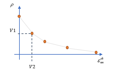
- RFAC
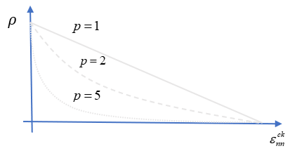
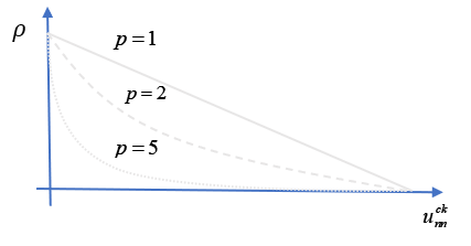
- Crack opening is expressed in the form of retention factor ( ) versus crack opening variable chosen for CRACK OPTION (STRN= , DISP or ENER= ). The series of values (V3, V4) defines a table of ( , ) or ( , ).
- PLAW
- Retention factor
is expressed in the form of a
power law. This power law evolves following the crack opening
variable chosen in the CRACK definition
(STRN=
, DISP or
ENER=
):
- FAILURE defines the limit of element deletion with the crack opening. Each principal stress over all directions of the element is used to compute a specific crack opening variable. NDIR is the number of principal directions that have reached the critical crack opening variable value V5 triggering the element deletion; at least 1 direction is mandatory. For shells there can be a maximal of 2 directions, and for solids 3 directions.
