Define Surface Probes
Use the Probes tool to define surface probes.
-
Create surface probes.
-
From the Setup ribbon, click the
Output
tool.
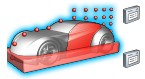
Figure 1. -
From the secondary tool set, click the surface probes of the
Probes tool.
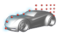
Figure 2.
-
From the Setup ribbon, click the
Output
tool.
- Optional:
Define the start time.
-
Click
 next to start iteration to change the
active input and click
next to start iteration to change the
active input and click  .
.
-
Enter a value for the start time.
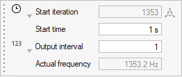
Figure 3.
-
Click
- Optional:
Define the refinement level.
-
Click next to output interval to change the
active input and click
 .
.
-
Enter a value for the refinement level..
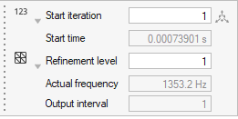
Figure 4.Note: The refinement level picks the lowest fractional output interval corresponding to the user specified refinement level.
The output interval is automatically set. -
Click
- Optional:
Define the target frequency.
-
Click next to output interval to change the
active input and click
 .
.
-
Enter a value for the target frequency.
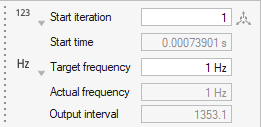
Figure 5.Note: The target frequency picks the closest fractional output interval corresponding the user requested target frequency. The output interval and actual frequency are displayed.
The output interval is automatically set. -
Click
- Optional:
Import and export surface probes.
- From the legend in the top-left of the modeling window, right-click the active probe set and select Probes table from the context menu.
-
In the dialog, select
 to import surface probes.
-
In the dialog, select
 to export surface probes.
For more information, see Import, Export, and Edit Output Controls. -
Change the color of probes.
-
Use the color picker to edit the color of the selected probes.
Tip: Create custom colors within the color picker by clicking
 .
.
-
Use the color picker to edit the color of the selected probes.
-
Move probes in the modeling window.
-
In the microdialog, select
 .
.
-
Use the graphical manipulators to move the probe.
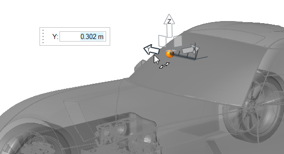
Figure 6.
-
In the microdialog, select
-
From the guide bar, complete one of the following:
- Select
 to confirm your selection and continue creating
sets of probe points.
to confirm your selection and continue creating
sets of probe points. - Select
 to
confirm your selection and exit the tool.
to
confirm your selection and exit the tool.
- Select