Run CAD Wrapping
Use the Wrap: CAD Wrap tool to create wrap from selected parts. CAD wrapping keeps the original geometry shape as it is and just fixes areas of issue.
If local and proximity controls are defined, they will override the default settings defined in this tool.
-
From the Discrete ribbon, click the tool.

Figure 1. -
Define any other relevant options.
- Per part wrap
- Perform the wrap operation on each part in the selection. Useful option if required to just make each part water-tight. No need to define seed node if this option is on.
- Split large elements
- Refine/split element input with longer edge than defined Size value. Keep this value around the average size you want on wrapped parts. Keep the value in of 15-20 mm range for better results.
- Stitch free edges
- Perform stitching on nearby free edges within the defined tolerance. A large value can result in mesh distortion. It is best to keep tolerance as 0.1 mm.
- Resolve overlaps
- Perform trimming and overlap on inputs. It will find elements in proximity within defined threshold and merge them before wrapping begins. Use this functionality to clear overlaps but not proximity elements. Side effect of a bigger threshold can be distortion of small features. Ideally, define the threshold smaller than the smallest feature, or around 0.1 mm.
- Maximum allowable gap
- Determines the size of gaps to ignore as well as details of features
to be captured.
Define this value bigger than the biggest leak/gap in the model. If there is no known/visible leak, define a relatively small value (5 mm) to capture all features.
Leaks are detected if a seed node is defined and if a gap in the input model exceeds the value define here.
Average Size defined in local controls will take precedent over the value defined here during wrapping.
- Auto seal
- Option to close big patches automatically. If on, it will detect leaks and will close the leaks. It may distort features in surrounding area causing them to leak.
-
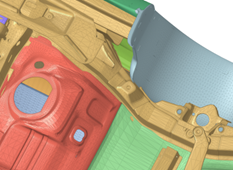
Figure 2. Input with gap and openings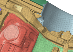
Figure 3. Gaps and openings sealed to get water-tight - Baffle treatment
- One of the steps in the wrapping process is to detect baffles and process them. Baffles in the wrapping process can be defined as floating zero thickness shells which do not form any enclosed region. They can cause images in the wrapping outcome.
- The following is a section cut image of a simple model. If
Maximum allowable gap is less than the gap
size < 39, and Baffle treatment is set to
Inflate Both Sides, you get the following
results.
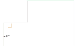
Figure 4. Input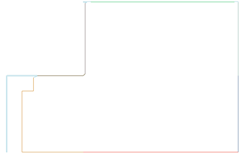
Figure 5. Wrap result with Inflate both sides option - Quality cleanup
- Turn on this option only if input mesh quality is very good. It will improve aspect ratio and proximity of wrapped result.