Connector groups are created and organized under the root of the Part Browser. A part is automatically created to house the new
connector group. To create a connector group:
Select the connectors you want to contain in the new group.
Drag the selected connectors onto the target connector.
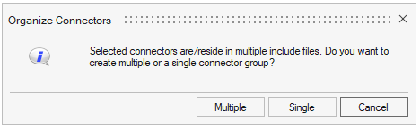
Note: If the
connectors are in different includes you will be prompted to create
either a single group or multiple groups. Figure 1.
Choose whether to create a single group or multiple groups.
Element Organization
Element organization is done through the Browser Configuration
dialog. You can set the element organization field to one of the following
options:
Connector group
Organizes the connector realization into components of the same name as
the connector group.
Automatic
Organizes the connector automatically based on its links. They can be
either general (all connector links are in the same subsystem or no
subsystem) or subsystem (one or more links are in multiple
subsystems).
Current include
Organizes the connectors into a current include when realizing a
connector.
Current component
Organizes the connectors to a current component on realizing.
Component ID
Organizes the connectors to a specified component ID on realizing.
To organize elements:
From the Connector Browser, right-click in white space
and select Configure Browser. The Browser
Configuration dialog opens.
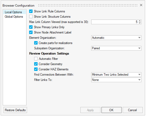
Click the Local Options tab in the left pane to
display local options.
In the Element Organization field, select the appropriate option. Figure 2.
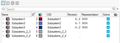
If you selected Automatic, in the Subsystem Organization field, select
either Paired (subsystem connectors create subsystems
to organize and realize based on connector links) or
Single (subsystem connectors create a single
subsystem to organize and realize).Figure 3.
Click OK.
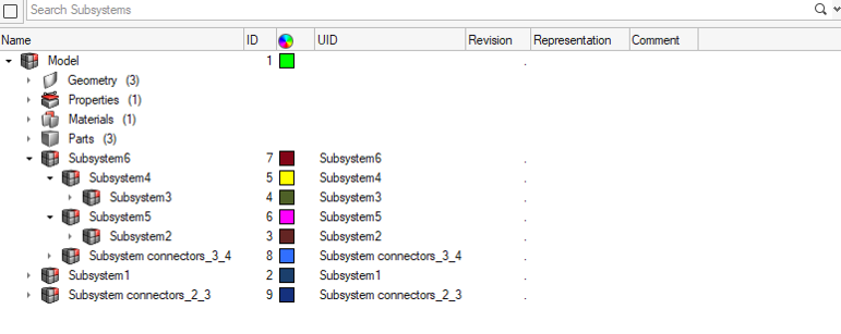
Connector Subsystems
Connector Subsystems are created by selecting the Automatic
option in the Element Organization field. The subsystem created is organized under
the common parent subsystem of the parts/components linked by the respective
connector. Figure 4.