For the most part, OptiStruct uses the same checks as
HyperMesh. However, OptiStruct
uses its own method of calculating Aspect Ratio, and it does not support 3D element
checks.
Aspect Ratio
Ratio between the minimum and maximum side lengths.
3D elements are evaluated by treating each face of the element as a 2D
element, finding the aspect ratio of each face, and then returning the
most extreme aspect ratio found.
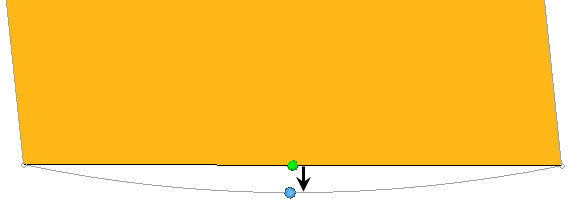
Chordal Deviation
Chordal deviation of an element is calculated as the largest distance
between the centers of element edges and the associated surface. 2nd
order elements return the same chordal deviation as 1st order, when the
corner nodes are used due to the expensive nature of the
calculations. Figure 1. Chordal Deviation
Interior Angles
Maximum and minimum values are evaluated independently for triangles and
quadrilaterals.
Jacobian
Deviation of an element from its ideal or "perfect" shape, such as a
triangle’s deviation from equilateral. The Jacobian value ranges from
0.0 to 1.0, where 1.0 represents a perfectly shaped element. The
determinant of the Jacobian relates the local stretching of the
parametric space which is required to fit it onto the global coordinate
space.
HyperMesh evaluates the determinant of
the Jacobian matrix at each of the element’s integration points, also
called Gauss points, or at the element’s corner nodes, and reports the
ratio between the smallest and the largest. In the case of Jacobian
evaluation at the Gauss points, values of 0.7 and above are generally
acceptable. You can select which method of evaluation to use, Gauss
point or corner node, from the Check Element
settings.
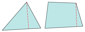
Length (min)
Minimum element lengths are calculated using one of two methods:
The shortest edge of the element. This method is used for
non-tetrahedral 3D elements.
The shortest distance from a corner node to its opposing edge
(or face, in the case of tetra elements); referred to as
"minimal normalized height".
Figure 2. Length (Min)
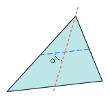
Skew
Skew of triangular elements is calculated by finding the minimum angle
between the vector from each node to the opposing mid-side, and the
vector between the two adjacent mid-sides at each node of the
element. Figure 3. Skew of Triangular Element
The minimum angle found is subtracted from ninety degrees and
reported as its skew.
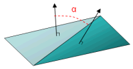
Warpage
Amount by which an element, or in the case of solid elements, an element
face, deviates from being planar. Since three points define a plane,
this check only applies to quads. The quad is divided into two trias
along its diagonal, and the angle between the trias’ normals is
measured.
Warpage of up to five degrees is generally acceptable. Figure 4. Warpage