Calculate Mass
Use the Mass tool to calculate the mass, center of gravity (COG), and moments of inertia (MOI) of the model.
-
From the Validate ribbon, click the Mass tool.

Figure 1. -
Click
 on the guide bar to set your
desired options.
- Results type
- Defines the calculation as Mass, Center of Gravity and Inertia, or, Mass values only.
- Consider Time Step Mass
- Activates the calculation of solver numerical added mass due to
elemental time step.Restriction: This option is only valid in the Radioss and LS-DYNA profiles.
- Time Step Definition
- Set the method to retrieve the Time Step value.Restriction: This option is only valid in the Radioss and LS-DYNA profiles.
- User Define: the Time Step Value field becomes active and has to be set.
- From Control Card: the time step value is directly read from the
*CONTROL_TIMESTEP keyword.Restriction: This option is only valid in the LS-DYNA profile.
- Axes
- Defines the coordinate system axes in which the CoG and MOI values are computed. It can be the Global System or a Local System. If Local System is selected, a System selector appears on the guide bar to select the system in the model.
- MOI Center
- Defines the center location used for the moment of inertias calculation. It can be "at CoG" or "at System Center". Example: If the Axes option is set to Global System, MOI Center set to "at System Center" means that MOI values are calculated around (0,0,0) point location.
- Consider Lumped Mass
- Allows you to consider the lumped masses for the calculation of the CoG and MOI on the component level. This option is off by default, which respects the solver behavior.
-
Restriction: This option is only valid in the Radioss and LS-DYNA profiles.
- Show center of gravity
- Enables the creation of a marker in the modeling window to visualize the CoG location of the model.
- CoG Node
- Creates a free node at the CoG location of the model.
- Context numerical format
- Defines the format of the numerical format and precision of the values exposed in the results table
- Use the drop-down menu to group values based on assembly or include.
-
Click Compute.
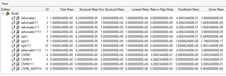
The detailed mass values are displayed in a table.

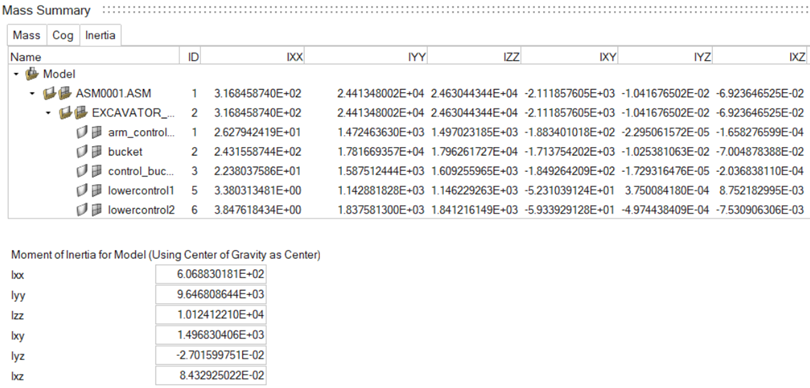
Figure 2.CoG and inertia selected as the Result Type, per component:
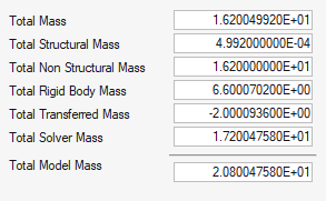
Figure 3.The relevant Total values are displayed at the bottom of the dialog.- Total Mass
- Represents the engineering mass as:
- Total Mass = Structural Mass + Non-Structural Mass
- Structural Mass
- Represents the physical mass of the structure, calculated from the property and material characteristics assigned to the FE mesh.
- Non-Structural Mass
- Represents the additional solver masses added on the structural mesh.
-
- In the LS-DYNA profile:
- *ELEMENT_MASS_PART
- *ELEMENT_MASS_PART_SET
- MAREA value in *SECTION_SHELL
- NSM value in *SECTION_BEAM
- Lumped Mass
- In the Radioss profile:
- /ADMAS/3
- /ADMAS/4
- /ADMAS/6
- /ADMAS/7
- Lumped Mass
- In the PAM-CRASH profile:
- NSMAS /
- NSMAS2 /
- In the LS-DYNA profile:
- Lumped Mass
- Represents the portion of the non-structural mass, which is distributed on structural nodes.
-
- In the LS-DYNA profile:
- *ELEMENT_MASS
- *ELEMENT_MASS_NODE_SET
- *ELEMENT_INERTIA
- *ELEMENT_SEATBELT_ACCELEROMETER
- In the Radioss profile:
- /ADMAS/0
- /ADMAS/1
- /ADMAS/2
- /ADMAS/5
- In the LS-DYNA profile:
- Mass in Rigid Body
- Represents the mass of the nodal rigid body elements in the collector.
-
- In the LS-DYNA profile:
- *CONSTRAINED_NODAL_RIGID_BODY
- In the Radioss profile:
- /RBODY
- In the LS-DYNA profile:
- Transferred Mass
- Represents the nodal mass transferred to the nodal rigid body elements or rigid Parts.
-
- In the LS-DYNA profile:
- Nodal mass transferred to *CONSTRAINED_NODAL_RIGID_BODY
- Nodal mass transferred to rigid *PART connected with CONSTRAINED_EXTRA_NODE or CONSTRAINED_RIGID_BODIES.
- The lumped mass defined on nodes is also transferred to the rigids.
- In the Radioss profile:
- Nodal mass transferred to /RBODY
- The lumped mass defined on nodes is also transferred to the rigids.
- In the LS-DYNA profile:
- Solver Mass
- Represents the mass as it is calculated by the solver.
-
- In the LS-DYNA profile:
- For deformable *PART, the Lumped Mass is not
considered:
Solver Mass = Structural Mass + Non-Structural Mass + Transferred Mass – Lumped Mass on non-rigid nodes
This value can be compared to the total mass of part in mass properties of part written in the d3hsp file.
- For rigid *PART, the lumped mass is
considered:
Solver Mass = Structural Mass + Non-Structural Mass + Transferred Mass
This value can be compared to the mass of rigid body in mass properties of rigid body material written in the d3hsp file.
- For deformable *PART, the Lumped Mass is not
considered:
- In the Radioss profile:
- The Lumped Mass is not considered into the /PART
mass.
Solver Mass = Structural Mass + Non-Structural Mass + Transferred Mass – Lumped Mass on non-rigid nodes
- The Lumped Mass is not considered into the /PART
mass.
- In the LS-DYNA profile:

Figure 4.- Total Mass
- Represents the total engineering mass of the model and is the sum of the values in the Total Mass column of the table.
- Total Structured Mass
- The sum of the values in the Structural Mass column of the table.
- Total Non-Structured Mass
- The sum of the values in the Non-Structural Mass column of the table.
- Total Rigid Body Mass
- The sum of the Mass in Rigid Body column and represents the total mass of the nodal rigid body elements in the model.
- Total Transferred Mass
- The sum of the Transferred Mass column of the table.
- Total Solver Mass
- The sum of the Solver Mass column of the table.
- Total Model Mass
- Represents the final total mass of the model as it is calculated by the solver:
-
- Total Model Mass = Total Solver Mass + lumped mass on
non-rigid nodes
For LS-DYNA, this value can be compared to the total mass in summary of mass written in the d3hsp file.
For Radioss, this value can be compared to the TOTAL MASS value written in the 0.out file.
- Total Model Mass = Total Solver Mass + lumped mass on
non-rigid nodes