Altair MotionView 2023 Release Notes
Altair Multibody Solutions 2023 Release Notes
Highlights
- New MotionView interface.
- Run workflow updates.
- Tracked vehicle solution updates:
- Track soft soil solution.
- Soft soil road visualization enhancements.
- Double Pin Track Link option in the Track Builder.
- New rolling systems available in the Track Builder.
- Vehicle Tools updates:
- New custom soft soil obstacle.
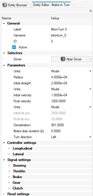
- Full vehicle events using the Entity Editor.
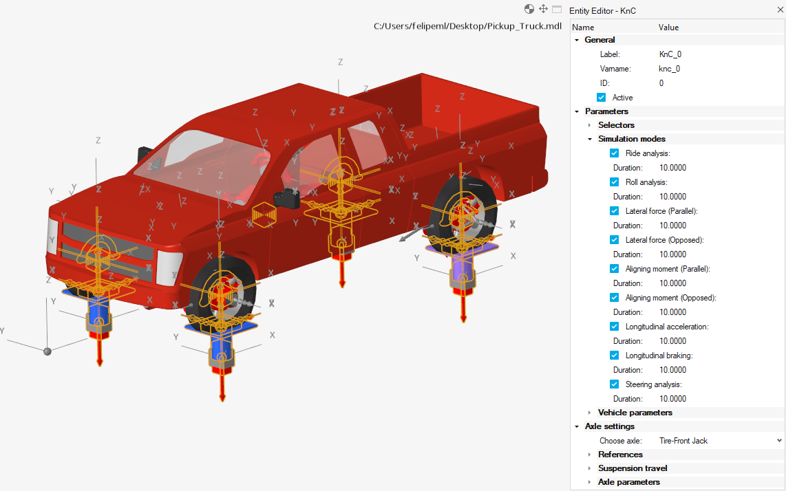
- Kinematic and Compliance analysis for a full vehicle.
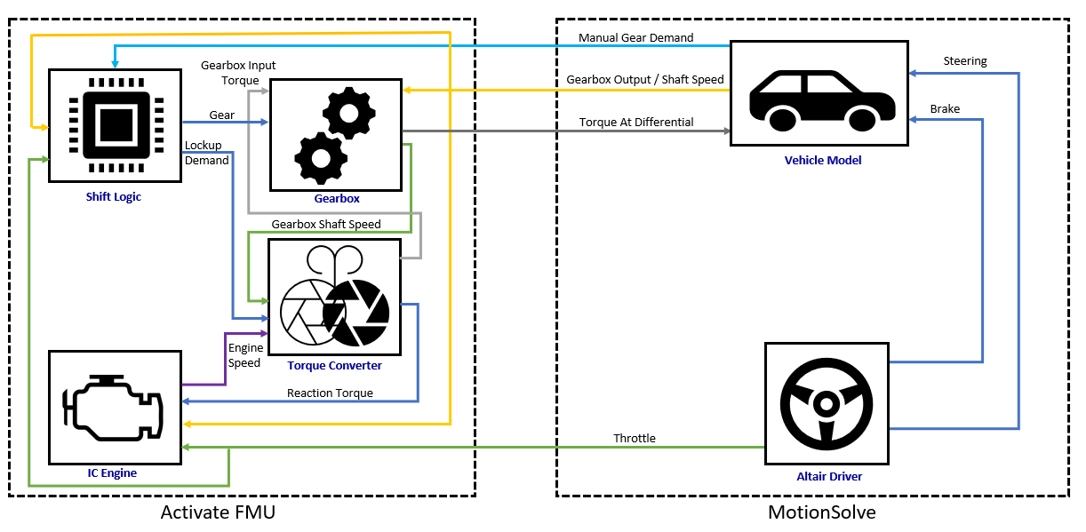
- Automatic transmission powertrain in the Vehicle Libraries.
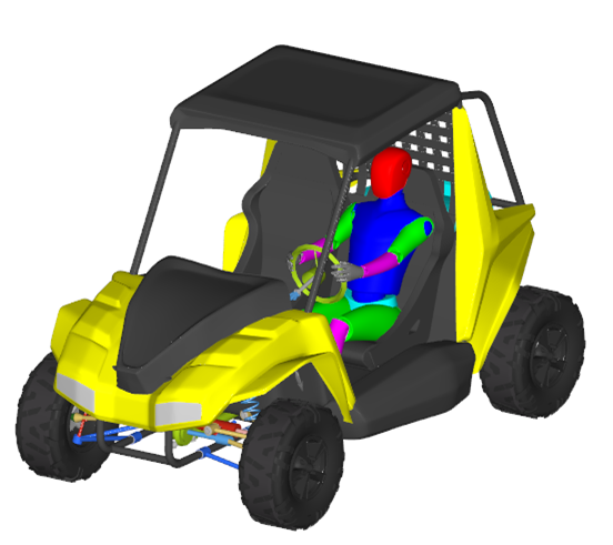
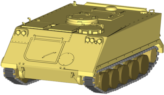
- New UTV and tracked APC example models.
- Soft soil road visualization enhancements.
- Updated Model Utility.
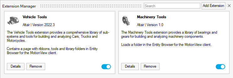
- Machinery tools extension.
New Features
- New Linear Results in Complex Nodal Displacement Format to _linz.H3D
- MotionSolve offers comprehensive analysis capabilities by enabling the study of linearized versions of your models at different configurations, including the model configuration, static equilibrium configuration, or configuration at the end of a transient simulation. By linearizing your model, MotionSolve accurately calculates the eigenvalues and normal modes. In previous versions, normal modes were saved as transient results in the H3D format for visualization in HyperView. However, in the latest version, MotionSolve saves complex nodal displacement to H3D files, named *_linz.h3d. This improvement allows HyperView to seamlessly perform modal animation and leverage the NVH Director feature, providing a consistent workflow and interface like other solvers, such as OptiStruct.
- The New MotionView Interface
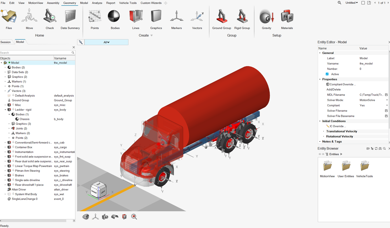
- The new MotionView interface is now mainstream. Classic MotionView has been retired and is no longer available from this version onward. All functionalities have been migrated to the new interface that is driven by a large ribbon at the top. Use the ribbon icons to enable model building workflows assisted by guide bars, microdialogs, dialogs, and entity editors.
- Entity Editors
- The following entities have an Entity Editor in the new interface: Systems, Analyses, Datasets, Templates, Forms, FMU, General Constraints, Outline Graphics, and Solver Arrays.
- Run Workflow Updates
- The interface to solve a model has been improved.
- Each analysis instance now carries the simulation settings
individually. For example, analysis type, end time, or
integrator settings can be modified and stored for each analysis
separately through its Entity Editor.
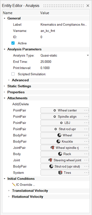
Figure 2. - A default analysis instance is now available. If the model does
not contain any other user-defined analysis, use this default
analysis to set the simulation parameters using the Entity Editor.
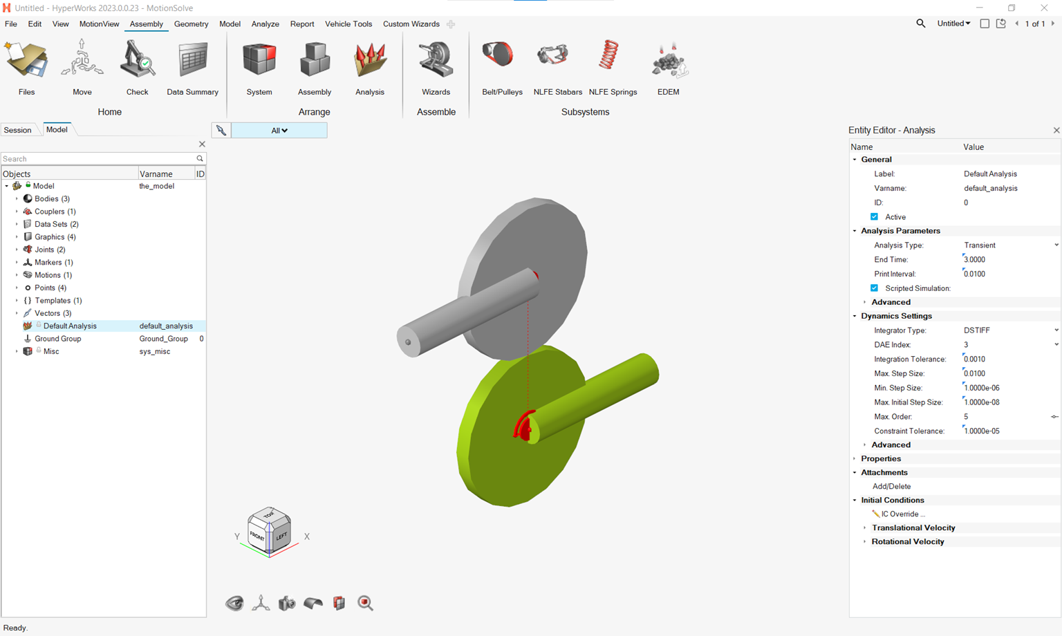
Figure 3. - The Run Settings dialog has been changed.
- It no longer contains the Analysis type and its related fields.
- The Output directory has been exposed upfront on this dialog.
- Analysis Settings have been renamed “Global Settings”.
- A separate run folder with the run name is no longer created. Instead, the run file is created in the output directory with the name containing the run name appended with the analysis variable name.
- The run history is organized based on models.
- A live animation during a run now displays the true deformation of the flexible body
- The result information is saved per analysis. In a model containing multiple analyses solved through live animation, the results per analysis can be animated by activating the analysis and using the results review context.
- Each analysis instance now carries the simulation settings
individually. For example, analysis type, end time, or
integrator settings can be modified and stored for each analysis
separately through its Entity Editor.
- Track Soft Soil Solution
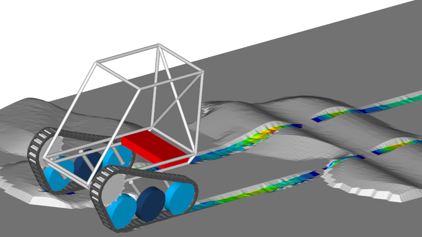
- The track solution is now available with the Altair Soft Soil model, providing a way to simulate the dynamic behavior of a track vehicle on a compressible surface, such as clay, dry sand, and regolith. Both tire and track models can be simulated together in the same soft soil terrain allowing you to capture the influence of the soil compaction due to track and tire ground pressure.
- Double Pin Track Link Option in the Track Builder
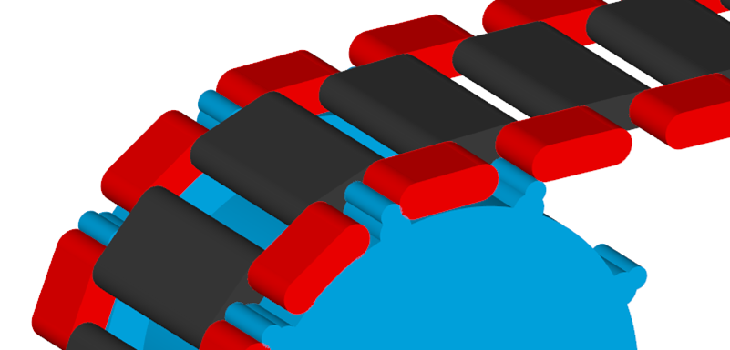
- A new track link option is available in the to build a track system using a double pin track link. Present in many military vehicle configurations, the double pin track links are joined to connector bodies that are usually in contact with the sprocket while the track links interact with the other rolling systems.
- New Rolling Systems Available in the Track Builder
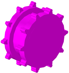
- Two new rolling systems are included in the . The double wheel and double sprocket allow better representation of the track system components.
- New Custom Soft Soil Obstacle
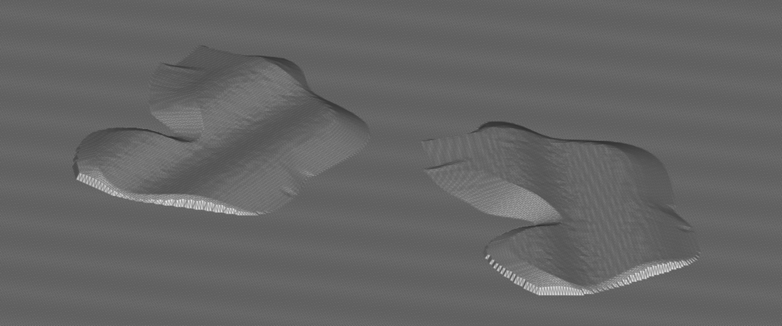
- Complementing the list of available soft soil obstacles, a new custom obstacle is now available. The custom obstacle allows the representation of any geometric shape as a soft-soil obstacle. It is defined as a Point Cloud Data (PCD) road added in the CUSTOM_OBSTACLE block in the soft soil road file. The PCD road can be created using a cloud of data points or an .fem file with triangular mesh created in HyperMesh.
- Full Vehicle Events Using the Entity Editor
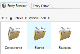
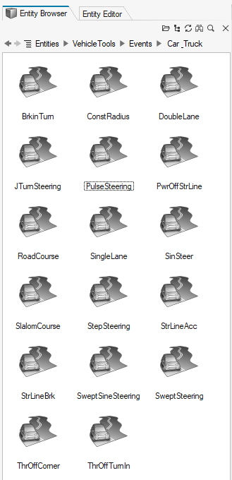
- The full vehicle events available in the Car and Small Trucks, Heavy Trucks, and Two-Wheeler libraries are now added through the Entity Browser under the Vehicle Tools extension.
- Kinematic and Compliance Analysis for a Full Vehicle
- A new Kinematic and Compliance event is available for full vehicle models, which you can use to design and validate the suspension characteristics of vehicles. The event is composed of nine subset analyses (Ride, Roll, Lateral and Longitudinal Forces, Align Moments, and Steering) that can be disabled as required.
- Automatic Transmission Powertrain in the Vehicle Libraries
- MotionView's Car and Small Truck Vehicle Library contains a new powertrain model of an internal combustion (IC) engine with an automatic transmission. The option to select the automatic transmission powertrain is available when building a full vehicle model with the Altair Driver under the Powertrain selection.
- New UTV and Tracked APC Example Models
- Two new models are available in the Example Models under the Vehicle Tools extension. The UTV model brings a new suspension type and parameters suitable for off-road simulation events. The Tracked APC example uses the new double pin track link on the track system and simulates the vehicle going over a few soft soil obstacles.
- Machinery Tools Extension
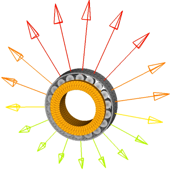
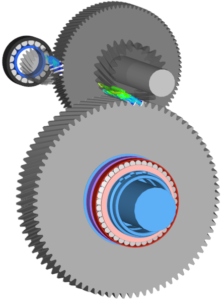
- A new MotionView extension designed to build and analyze machinery components is now available. The Machinery Tools extension contains a library of bearings and gears that can be used to model gearboxes, drive trains, engines, and similar mechanisms, using a minimum amount of time.
- Ribbon Hints
- Ribbon hints have been added to help identify tools that have multiple
pick targets or open a secondary ribbon. They are small indicators that
appear in the ribbon between a tool’s icon and label. The number of dots
represents the number of pick targets in a tool, including some that are
hidden until hovering over the tool.

Figure 16.
Enhancements
- Enhanced Reference Guide for MSolve API
- A detailed MSolve reference guide has been added to MotionSolve help. This manual provides detailed usage information for the Python API of MotionSolve, msolve. The reference guide contains a brief overview of the API, and a style conventions. The API documentation provides a comprehensive description of the available objects, methods, and functionalities. The manual contains three sections: the msolve section, which is the integral package of the API, and the two extensions of msolve, Optimization and Machinery.
- Total Kinetic Energy for Rigid Body is Written in _linz.mrf
- The total kinetic energy for a rigid body is written in the _linz.mrf. Plot the total kinetic energy in HyperGraph and use HyperStudy for further sensitivity, DOE, and optimization analysis.
- Distinguish Kinematic and Other States that Contribute to the Total Number of Independent Coordinates
- MotionSolve writes the breakup of kinematic independent coordinates and
other states which are from a control state equation, differential
equation, and so on, that contribute to the total number of independent
coordinates.
INFO: Total Number of Independent Coordinates = 1 (Kinematic DoF: 1, Other States: 0) - Soft Soil Road Visualization Enhancements
- Post-processing soft soil results in HyperView includes five new contour outputs: displacement, plastic sinkage, elastic sinkage, soft soil normal stress, and soft soil shear stress. Use these output options to quickly assess the tire and track dynamic behavior on soft terrains.
- Update Model Utility
- Use the Update Model Utility in the Vehicle Tools extension to update models that were created in older versions of HyperWorks. This utility replaces the AutoEntities, AltairDriver and Events with the newer Entity Editor-based entities.
- RigidGroup Context Enhancement
- Rigid group creation context no longer requires you to use the Ctrl key while selecting multiple bodies.
- Wizard Update
- The Wizard language includes text messages on the Wizard's pages.
Resolved Issues
- Log file with repeated energy distribution when HTML report is turned on.
- Analytical contact between the Box and Cylinder face.
- Memory overflow in a triamesh contact.
- Creating more than one Belt Pulley system using the Belt Pulley tool fails.
- When imported, external graphics in ADM gets all components instead of the referred one.
- MotionView crashes when importing an ADM with labels that have additional quotes.
- Pre-loading NLFE through the available script in the install is incorrect.
- Add entity through a right-click context option in a browser creates entities in Model instead of the parent system.
- The Contact side that is highlighted does not reset during a Live animation of the run.
- Load set file for contact prediction cannot be specified in the file selection from the Entity Editor.
- Error dialog appearing while solving a Live run cannot be dismissed.
- Cannot select a new file for the load set file under Contact Prediction in the Flexible Body Entity Editor.
- Run time error related to compliant joint during Live animation.
- Snapshot MDL from models containing systems through DefinitionInclude is corrupted with Set statements, resulting in errors while loading the MDL.
- Entity editor for entities is blank when in Results Review mode.
- Point picking mode is lost when you hover in the modeling window with the MultiPoint collector active from the Entity Editor.
- Post-processing soft soil results no longer requires loading the model results .h3d and the road results .h3d with the Overlay option in HyperView. The road results are now included in the model results.
- The MBD-Vehicle Dynamic Tools preference loads a Vehicle Tools menu option containing the features identical to those available in the Vehicle Tools extension. This menu option was removed, and the Vehicle Tools extension contains all Vehicle Tools features.
Known Issues
- Automated reports for the new full vehicle Kinematic and Compliance event are only available for two-axle vehicles with two wheels each.
- Obstacles with a material defined as rigid are currently not supported for track models on soft soil.
- Suspension models (front end of vehicle/rear end of vehicle) built from the Assembly Wizard now include tire entities in them. The suspension analyses (task wizards, accessed from the Events ribbon) have been updated to include the tire systems as attachments. In MotionView 2023, if you load a suspension model that was created in an older version of MotionView and attempt to add an analysis, the tire attachment fails to resolve. To mitigate this, after adding the analysis, delete the Tires attachment, then delete the statement (<Deactivate/>) that deactivate the tire forces within the template that contains the solver command lines.
