OptiStruct supports the Rotor Dynamics functionality in
the following solution sequences.
Frequency Response Analysis
The response of a structure with rotating components to a specified external excitation can be determined using the rotor dynamics functionality in frequency response analysis.
Asynchronous Analysis (RGYRO=ASYNC)
If ASYNC is specified in the RGYRO Bulk Data Entry, the
rotors within the structure have user-defined spin rates. The excitation frequency
(FREQi Bulk Data Entries) is independent of the reference
rotor speed defined in the RGYRO Bulk Data Entry.
Synchronous Analysis (RGYRO=SYNC)
If SYNC is specified in the RGYRO Bulk Data Entry, the
reference rotor spin rate is equal to (or synchronous with) the excitation
frequency. The reference rotor speed is not input via the RGYRO
Bulk Data Entry and the FREQi Bulk Data Entries values are used
in this analysis.
Complex Eigenvalue Analysis
The eigenvalues and critical speeds of a structure with rotating components can be determined using the rotor dynamics functionality in complex eigenvalue analysis.
Asynchronous Analysis (RGYRO=ASYNC)
If ASYNC is specified in the RGYRO Bulk Data Entry, the
rotors within the structure have user-defined spin rates via the
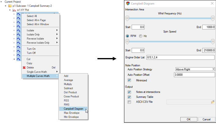
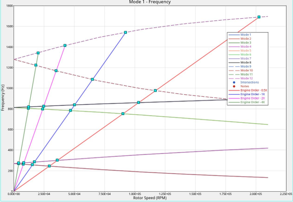
RSPEED entry and the Campbell Diagram can be plotted to find
the critical speeds. Additionally, since the calculated eigenvalues are complex, you
can determine unstable modes by studying the real parts of the calculated
eigenvalues. If the real part of a complex eigenvalue is positive, then the
corresponding system mode is unstable.
Synchronous Analysis (RGYRO=SYNC)
If
SYNC is specified in the
RGYRO Bulk Data Entry, only the
critical speeds are calculated as the rotor speeds are equal to the whirl
frequencies. These critical speeds can lead to structural resonance and the design
should be modified to change its whirl frequencies or the operating rotor spin rate
should be limited to avoid reaching the critical speeds.
Note: In a
Frequency Response Analysis, the Synchronous Analysis (SYNC)
option is generally used to model rotors with an inherent unbalance. The rotor
unbalance can be specified as a force or via the UNBALNC Bulk
Data Entry. The analysis is synchronous because the unbalanced load vibrates at
the whirl frequency of the system which is equal to the rotor spin
speed.
Frequency Response Analysis (ASYNC)
Asynchronous Analysis is activated using the
RGYRO=
ASYNC option. Frequency Response
Analysis in rotor dynamics involves defining the excitation either as an external
varying load as a function of frequency or as a rotor unbalance via the
UNBALNC Bulk Data Entry (or as a force that simulates the
effect of the rotor unbalance). Asynchronous frequency response analysis in
OptiStruct is designed for an external varying force at a
specific set of frequencies. The following equation implements the external loading
functionality in
OptiStruct. The rotor speeds should be
specified by you for Asynchronous Frequency Response Analysis.
(1)
The response of a system with rotating components to an external load in the
frequency domain is calculated based on Equation 1.
Frequency Response Analysis (SYNC)
Synchronous Analysis is activated using the
RGYRO=
SYNC
option. Frequency Response Analysis in rotor dynamics involves defining the
excitation either as an external varying load as a function of frequency or as a
rotor unbalance via the
UNBALNC Bulk Data Entry (or as a force
that simulates the effect of the rotor unbalance). Synchronous Frequency Response
Analysis in
OptiStruct is designed to calculate the
response of a system with a rotor unbalance. The following equation implements the
rotor unbalance functionality in
OptiStruct. The rotor
speeds are determined from the
FREQi entries for Synchronous
frequency response analysis.
(2)
The response of a system with rotating components to a rotor imbalance which is considered as a
force acting in the frequency domain is calculated based on Equation 2.
Frequency Response Analysis with WR3, WR4 and WRH (ASYNC)
Parameters
PARAM,
WR3,
PARAM,
WR4, and
PARAM,
WRH can be used to avoid frequency
dependent calculation of the rotor damping and circulation terms in systems with
multiple rotors. The frequency values in the circulation damping terms are replaced
with the values of the parameters as shown in
Equation 3.
PARAM,
GYROAVG should be set to
-1 to be able to bypass frequency dependent look-up and use the
WR3,
WR4, and
WRH
values.
(3)
Frequency Response Analysis with WR3, WR4 and WRH (SYNC)
Parameters
PARAM,
WR3,
PARAM,
WR4 and
PARAM,
WRH can be used to avoid frequency
dependent calculation of the rotor damping and circulation terms in systems with
multiple rotors. The rotor speeds can be calculated as a linear function of the
reference rotor spin rate (see description of terms below). The reference rotor spin
rate values in the circulation damping terms are replaced with the values of the
parameters as shown in
Equation 4.
PARAM,
GYROAVG should be set to
-1 to be able to bypass frequency dependent look-up and use the
WR3,
WR4, and
WRH
values.
(4)
Complex Eigenvalue Analysis with WR3, WR4 and WRH (ASYNC)
The eigenvalues and critical speeds of a structure with rotating components can be
determined using the rotor dynamics functionality in Complex Eigenvalue Analysis. In
Asynchronous Analysis the critical speeds can also be determined by plotting the
Campbell diagram for frequencies specified using the
RSPEED Bulk
Data Entry. The parameters
PARAM,
WR3,
PARAM,
WR4, and
PARAM,
WRH can be used to replace the
values of
WR3,
WR4, and
WRH
in
Equation 5.
(5)
Complex Eigenvalue Analysis with WR3, WR4 and WRH (SYNC)
Only the rotor speeds are required to perform the Synchronous Complex Eigenvalue
Analysis as the whirl frequencies are equal to the reference rotor spin rates. Only
the critical speeds are output as a result of this analysis. The parameters
PARAM,
WR3,
PARAM,
WR4, and
PARAM,
WRH can be used to replace the
values of
WR3,
WR4, and
WRH
in
Equation 6.
(6)
Static
For Static Analysis, the following moment term is added to the load vector at each
rotor grid.
(7)
Linear and Small Displacement Nonlinear Direct Transient Analysis
The rotor speeds (
) are time-dependent in Transient Rotor Dynamics. The
displacement equation (with WR3, WR4, and WRH) is:
(8)
Where,
- Reference rotor spin rate
- Spin rate of rotor "" as a function of the reference rotor
spin rate.
- Determined for each excitation frequency or it can be calculated as a
linear function of the reference rotor spin rate:(9)
- Where, and are scaling factors calculated from the
relative spin rates defined in the RSPINR Bulk Data
Entry.
- Structural mass
- Viscous damping of the support
- Rotor viscous damping
- Rotor hybrid viscous damping
- Rotor mass
- Rotor stiffness
- Rotor material damping
- Rotor hybrid material damping
- Circulation, due to rotor viscous damping
- Circulation due to rotor hybrid viscous damping
- Circulation, due to rotor mass
- Circulation, due to rotor structural stiffness
- Circulation, due to rotor material damping
- Circulation, due to rotor hybrid material damping
- Stiffness of the support
- Mass of the support.
- Material damping of the support
- Hybrid viscous damping of the support.
- Hybrid material damping of the support.
- Number of rotors in the model
- Displacement as a function of frequency
- Displacement as a function of reference rotor spin rate
- External excitation as a function of frequency
- Unbalanced load as a function of reference rotor spin rate (via
DAREA or UNBALNC Bulk Data
Entries)
- Structural damping value of the support defined using
PARAM,G
- Structural damping value of the rotor defined using
PARAM,G
- Angular velocity vector obtained from a pertinent
RFORCE Bulk Data Entry
WR3, WR4, and WRH are
defined via the parameters PARAM, WR3, PARAM,
WR4, and PARAM, WRH. They may also be rotor
dependent and specified on RSPINR and RSPINT
Bulk Data Entries. These parameters allow you to bypass frequency-dependent looping
by specifying the equivalent “average” excitation frequencies when PARAM,
GYROAVG, -1 is specified.
The general form of a circulation damping term is given as:(10)
Where,
- Regular damping matrix
- Skew-symmetric rotation matrix defined as follows in the rotor
coordinate system
(11)
This 6x6
matrix is repeated for each grid along the rotation
axis of the rotor. The individual
matrices are added in the diagonal of the global
skew-symmetric matrix.
- Gyroscopic matrix defined in a rotor coordinate system
as:(12)


