Measures

Use the Measure tool to measure length, angles, radii, areas, volumes, centers of gravity, and bounding boxes.

Note: The following covers measures in HyperMesh.

For information on measures in HyperView, see the Results Data chapter. For measures in MediaView, see Media Files.

Measure Length, Angles, and Radii

Draw, length, angle, and radius measurements in the modeling window.

  1. From the Home tools, click the Measure tool.


    Figure 1.
  2. Optional: On the guide bar, click to adjust visualization options.
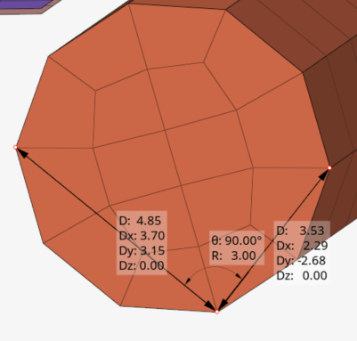
  3. Draw lines to measure length, angles, and radii.
    • Measure length by left-clicking on geometry to create start and end points.
    • Measure an angle or the radius of a circle by drawing two lines that start or end at the same point.


    Figure 2.
  4. Extract additional information from the measurements in the following ways:
    • Click on a length measurement to expand or collapse the individual measurement components (Dx, Dy, Dz).
    • Right-click on a measurement to copy individual line items or all measurement values in a selected label. When you copy all, the component labels are retained so you can distinguish between the values. When you copy an individual component, only the value is kept. This way you can quickly paste into another field.
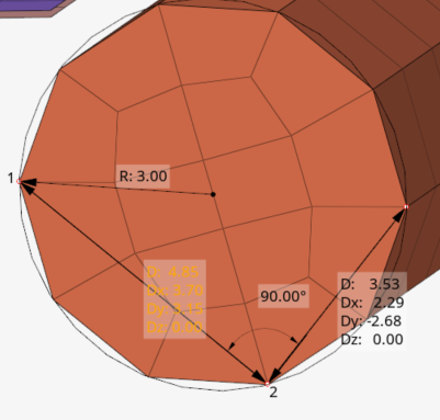
    • Right-click on the radius value to show/hide the circle that represents the three points contained within the two length measurements.
    • Hover over a length measurement to view the start (1) and end (2) points of the line. This gives you a reference for the component values.


    Figure 3.
Tip:
  • Use snap points to draw lines that are perpendicular or tangent to other lines, and snap to predefined points on your model such as end, middle, center, and intersection points.
  • Use the dimensioning option to modify distance, components, and angle values for selected nodes or points. These values can be in reference to a local system.

Calculate Summary Measurements

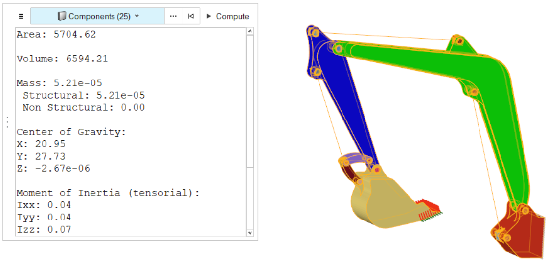
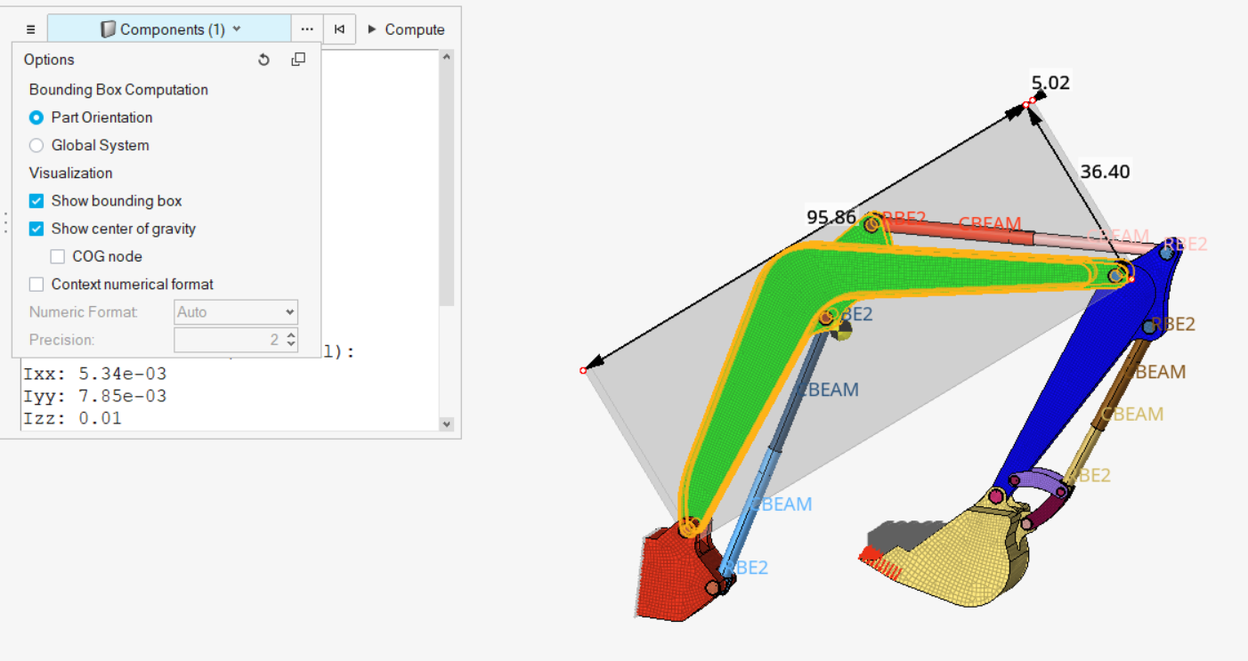
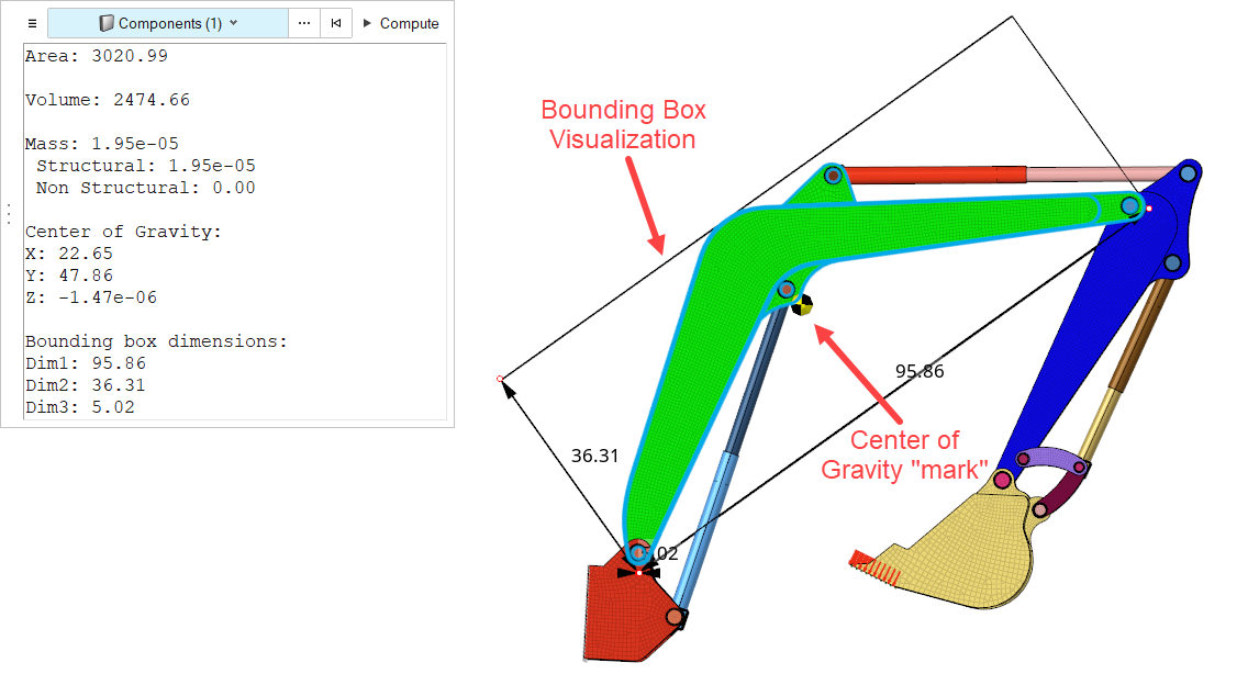
Summary measurements include areas, volumes, centers of gravity, bounding boxes, and the cumulative lengths of lines.
  1. From the Home tools, click the Measure tool satellite icon.


    Figure 4.
  2. Optional: Click in the microdialog to adjust bounding box orientation and visualization options, such as plotting the center of gravity (COG) and optionally creating a node at the COG location.
  3. Select entities to measure in the modeling window.

    The supported entity types are: components, elements, solids, surfaces, assemblies, and lines.

    Based on the entity type, the available measurement information may be restricted. For example, since geometries do not have mass, any measurements of solids will not include mass-based calculations or center of gravity.

  4. Click Compute to generate measurements for you selection.


Figure 5.


Figure 6.


Figure 7.