Specify Wheels

Identify the components that represent the model's wheels.

When modeling a wheel, a wall boundary condition is prescribed and a rotational velocity is applied.

You need to select the parts forming the wheel, for example tire and rim. All other parameters like center of rotation, axis of rotation, and the angular velocity (in RPM) are computed automatically. If multiple parts are selected, VWT will group the parts into one or more wheels. For example, if you select the brake disc, the rim and the tire of the left front wheel, all three parts will be identified as wheel_1. If you also select the rim and the tire of the left rear wheel, those parts will be grouped into wheel_2.

Identify wheels in the following ways:

  • Use the Identify Wheels tool.
    1. From the Setup ribbon, click the Identify Parts tool.


      Figure 1.
    2. From the secondary tool set, click the Create Wheel tool.


      Figure 2.
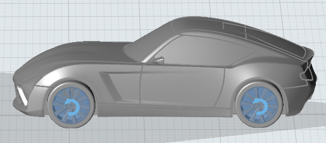
    3. Select the components that represent the wheels.
      For parts that form one wheel, the axis of rotation and a curved vector is displayed in the modeling window.
    4. Define the RPM and the coordinates of the axis of rotation.
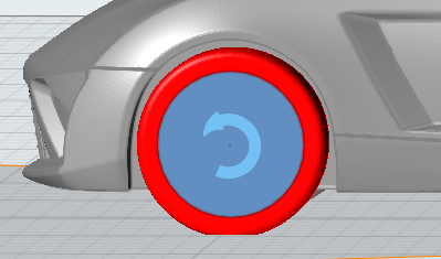
      1. Define the RPM by double-clicking the curved vector and entering a value in the microdialog.


        Figure 3.
        Tip: To reset this value to what was automatically calculated by VWT, click .
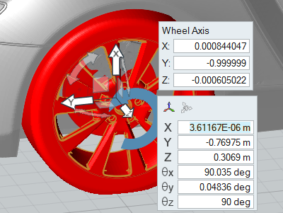
      2. Define the axis of rotation by double-clicking on the blue axis. Enter exact x, y, and z coordinates in the microdialog, or use the Move tool to interactively modify the axis. Left-click on the origin of the Move tool to orient the tool using precise values.


        Figure 4.
  • Right-click on a part in the modeling window or the Model Browser and select Identify As > Wheel from the context menu.
  • Select a part in the modeling window or the Model Browser then change the Identify As field to Wheel in the Property Editor.
Parts which are identified as a wheel are marked in the Model Browser with a wheel symbol.
Tip: Open the Property Editor and review the parameters associated with a particular wheel by left-clicking on parts identified as wheels in the Model Browser.

Define MRF Regions

MRF regions define a volume in which the governing equations are solved in a rotating reference frame. This transformation of the equations can lead to higher accuracy for rotating bodies due the addition of centrifugal and Coriolis forces.

  1. From the Setup ribbon, click the Identify Parts tool.


    Figure 5.
  2. From the secondary tool set, click MRF tool.


    Figure 6.
    A guide bar appears below the tool.
  3. Make sure Wheel is active on the guide bar then select a wheel in the modeling window.
    Parts previously identified as wheels are automatically grouped together.

    The angular velocity and center of rotation of the rotating frame are extracted from the wheel definition.

  4. On the guide bar, click MRF.
  5. In the modeling window, select regions to solve in the rotating frame.
    Regions solved in the rotating reference frame need to form closed volumes.


    Figure 7.
  6. On the guide bar, click .


    Figure 8.

    The MRF region is marked in the Model Browser.