Aerospace Composite Tools

Aerospace tools for working with composites.

PCOMP From CSV

PCOMP from CSV generates HyperMesh composite properties from data defined in a .csv file.

The required file format is shown in the table below. Layers of a property must share a single material ID and thickness. If this is not your use case, refer to Data I/O Spreadsheets for other options.

From anywhere in the HyperMesh app, press Ctrl+F to bring up the search bar in the top right, then search “PCOMP from CSV. In the Import file field, browse to the appropriate file and then click Create.

Table 1. File Format
PCOMP ID Material ID Thickness Orientation              
1 1 0.01 -45 0 45 90 90 45 0 -45
2 1 0.01 0 90 0 90        
11 5 0.02 30 0 30          

Shell To Solid Conversion

The Shell To Solid Conversion tool provides functionality to generate solid elements and material orientations from a ply based shell model.
Restriction: Only available in the Nastran, Abaqus, and OptiStruct solvers.
  1. From anywhere in the HyperMesh app, press Ctrl+F to bring up the search bar in the top right, then search “Shell to Solid COnversion
  2. In the Select entities field, select entities on which to perform shell to solid conversion.
    • Laminates
    • Plies
  3. In the Solid Elems field, select an option that controls the number of solid elements generated through thickness.
    • Create solids for each layer – generate single solid elements for each input ply layer.
    • Create single solids for all layers – generate single layered solid element through thickness. Output is either continuum shell of layered solid depending on the solver profile, element type setting (can be changed from 2D or 3D > elem types > 2D & 3D panel under penta6 and hexa8) and template property.
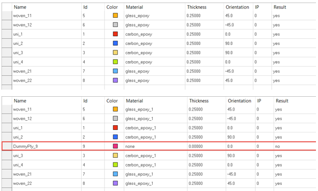
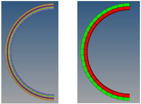
    • Create multiple solids using dummy ply separation – generate multiple layered solid elements through thickness. The number of layered solid elements is determined by the number of “Dummy Plies” in the laminate. Output is either continuum shell or layered solid depending on the solver profile, element type setting (can be changed from 2D or 3D > elem types > 2D & 3D panel under penta6 and hexa8) and template property.
  4. In the Component field, select the method for controlling solid elements generated in conversion:
    • Create comp for each ply – a new component is created for each input ply
    • Current collector – all solid elements created are placed in the current component
    • Create single comp for all plies – a single new component is created
    • Use existing shell component – solid elements are placed in the component containing the shell element from which they are generated
  5. Select Fill gaps to create pyra and penta elements to fill voids created by ply drops.
  6. Select Delete Shells to delete shell elements of ply-based model after solid elements are created.
  7. Select Create Props to create solid composite properties assigned to created solid elements.


    Figure 1.


    Figure 2. Dummy Ply for Create Multiple Solids Using Dummy Ply Separation