Partition Solids for Mappability
Before you can successfully solid mesh a model, ensure that the solids have been partitioned so that they are either one directional or three directional mappable.
Solid (3D) meshing can be done automatically, just like 2D shell meshing, but often requires that complex parts be partitioned into groups of smaller, simpler, connected solids instead of one large complex solid. In solid meshing, the ability to be meshed is referred to as mappability.
Use the Mappable visualization mode to review solid partitioning for mappability. The “Mappable” mode color codes the solids within the model according to whether the solids are solid meshable. The ignored map, not mappable, 1 directional map, and 3 directional map all relate to the mappable state of the solids.
-
From the View
Controls toolbar, set the geometry visualization mode to
Mappable.
The solid is color codes according to its mappability state.
- Blue
-
Solid has not been edited, and therefore cannot evaluated for mappability.
- Orange
-
Solid has been edited, but remains completely unmappable (further partitioning may enable mapping).
- Yellow
-
Solid is mappable in 1 direction.
- Green
-
Solid is mappable in three directions. This is very rare.
Figure 1. . The first cube is mappable in 3 directions, but if a corner is split off it becomes mappable in only 1 direction, and the corner is not mappable without further partitioning.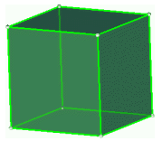
Partitioning Solids for Mappability
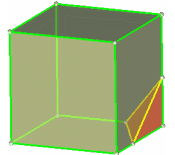
Figure 2 shows that one trim of the model by a single surface (the top surface of the rectangular shaft, in this case) has created two additional solids within the model. One solid remains in the ignored map state (blue), one is now not mappable (orange) and one is one directional mappable (yellow - transparent).
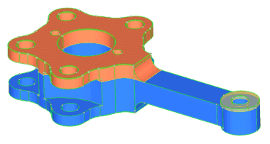
Figure 2.

Figure 3.
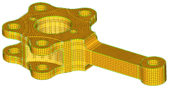
Figure 4.
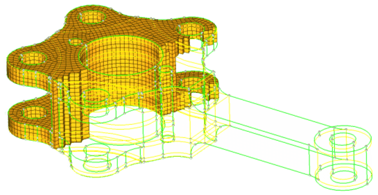
Figure 5.