Train a Machine Learning Model
Train a machine learning model based on labeling information it contains.
-
From the Assembly ribbon, click the tool.

Figure 1. -
Click Train.
After training a machine learning model, a binary file (<classifier_name>_<train_iteration>.aic) containing all training information is saved in the Classifier folder. If you add new labels to a classifier or you modify existing label assignments, retrain the machine learning model to apply the changes.Note: The value of <train_iteration> increments by one after every successful training operation. The number of train iterations starts at 0 and the <train_iteration> suffix is appended to the file names only when train_iteration > 0.
You can use the resultant binary (.aic) files from model training on different machines. As a result, an advanced user can create the classifiers and train the machine learning models to provide files for other users to perform part classification, eliminating the need to train a classifier (See Add Trained Model File).
Tip: From the guide bar, click and select Generate Log
File, if necessary. The log files
(<classifier_name>_<train_iteration>_log.txt)
are saved to the Classifier folder after training a machine learning
model.
and select Generate Log
File, if necessary. The log files
(<classifier_name>_<train_iteration>_log.txt)
are saved to the Classifier folder after training a machine learning
model.
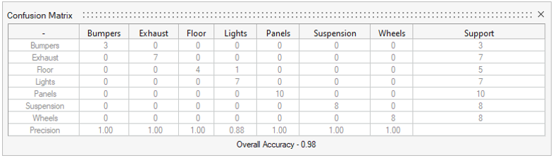
Figure 2. Confusion Matrix
Each row shows the label name and the total number of parts given that label by the user. This sum is displayed under Support.
- Precision
- The ratio of the number of correctly predicted labels of a given type to the total number of predictions of that same label. Provides insight into the ability of the machine learning model to predict the label correctly.
- Support
- The total number of parts with each label (user defined).
- Overall Accuracy
- The total ratio of correct predictions to the total number of predictions.
The Floor row displays a "4" under the Floor column and "1" under the Lights column. This means there were five Floor labels given to parts by the user, as confirmed by the total in the Support column.
A "4" in the Floor column indicates that the machine learning model predicted the Floor label to have four parts. The precision is 1 because each time it predicted that a part was a Floor, it was correct.
For the Lights row, the number "7" in the Support column indicates that there were seven assigned Light labels to parts. However, the Lights column display "1" under Floor and "7" under Lights. This means the machine learning model predicted eight parts to be lights; seven times it was correct, but once it predicted a part to be a light that was assigned the label Floor. Therefore, the precision of predicting Lights is 7/8, or 0.88.