Use the Autoshape function to automatically generate multiple shapes for individual
handles or domains.
This feature is intended for shape optimization and can be used to quickly generate
many shapes to be used as shape variables. One suggested use is to create handles
across the surface of a solid part and use Autoshape to generate well-behaved shapes
for those handles moving normal to the surface of the part. OptiStruct can be used to optimize the surface shape of the
part using these shapes. For linear shapes, a biasing factor of 2 is
recommended.
From the Morph ribbon, click the Shapes tool.
Figure 1.
The Edit Shapes dialog opens.
Right-click in the Edit Shapes dialog and select
Autoshape from the context menu.
Select the type of shapes to create.
Option
Description
Linear shapes
Move the handle using the standard morphing procedure.
Spline shapes
Use a spline algorithm to smoothly apply the shape across the
domain.
Polynomial shapes
Use a polynomial algorithm to smoothly apply the shape across the
domain.
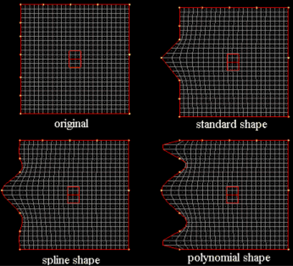
Figure 2.
Figure 2 shows autoshapes that been created for the handles along
the left side of the mesh. In each example, one of the autoshapes has been
applied. The standard shape in this case is angular but will be more curved
if handle biasing is used (see Set Biasing). The spline
shape creates a smooth shape that runs across the entire length of the edge
domain as does the polynomial shape, but the spline shape is more
controlled.
Note: When all the spline or polynomial shapes for a given
domain are applied, the resulting perturbations for the nodes along the
domain sum to the same amount, so if your domain is flat when the shapes
are unapplied, as shown in Figure 2, it will also be flat when the shapes are all
applied by the same factor. You can create a Fourier-type series with
smoothness ensured across the handles.
Select handles, for linear shapes, or domains, for spline or polynomial
shapes.
Shapes will be created at the selected handles or at the handles lying on the
selected domains.
Select the direction the handles will be moved in when creating shapes.
Choose the direction that the shape is applied in. For along element normals
and along vector HyperMesh generates one shape for
every selected handle in the direction normal to the surrounding shell elements
at the given magnitude. For XYZ components, HyperMesh generates up to three shapes for every handle selected, based on the
directions which you have checked.
Option
Description
Along XYZ axes
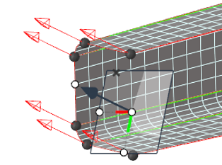
Figure 3 shows the preview vectors for the same six handles
using XYZ components.
Note: The Along XYZ axes option creates a shape in
each of the selected directions at the given magnitudes. Therefore,
if you select two handles and all three XYZ components, six shapes
are generated, one in each of the X, Y, and Z directions for both
handles.
Figure 3. By XYZ
Restriction: This option is only available when the
type of shape is set to Linear
shapes.
Along vector
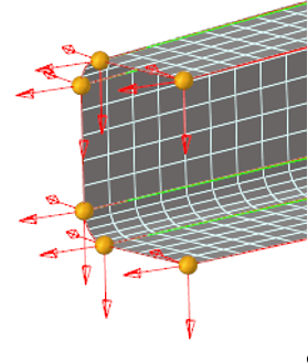
Figure 4 shows the preview vectors for the same six
handles using by vector. This option requires you to specify a
vector by using the manipulator.
Figure 4. Along Vector
From the drop-down menu, choose use all
elements or use selected
elements.
Along element normals
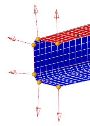
Figure 4 shows the preview vectors for six handles using
element normals. Figure 5. Along Normal
From the drop-down menu, choose use all
elements or use selected
elements.
Use shape
Use shape option applies only to spline or polynomial types. You can
use a shape to define the perturbation vectors for the handles. The
selected shape may have been saved as node perturbations or handle
perturbations. In either case, the shape will be converted to node
perturbations and the perturbations found at the selected handles will
be used.
Restriction: This option is not supported for linear
shapes.
From the System drop-down menu, select Global or
Local coordinate system depending on which
corresponds to the X, Y, and Z directions.
Restriction: This option is only available when the direction is set
to Along XYZ axes.
Choose whether to base the direction on the normals of all elements, or on only
the normals of elements that you select from the element selector.
Restriction: This option is only available when the direction is
set to Along element normals.
Handles usually
touch more than one element and the average normal for those elements is used
for the handle.
Select the Preview check box to show the vectors at the
handles where the shapes will be created.